Information processing apparatus, information processing method, movement control apparatus, and movement control method
- Summary
- Abstract
- Description
- Claims
- Application Information
AI Technical Summary
Benefits of technology
Problems solved by technology
Method used
Image

Examples
first embodiment
1-1. First Embodiment
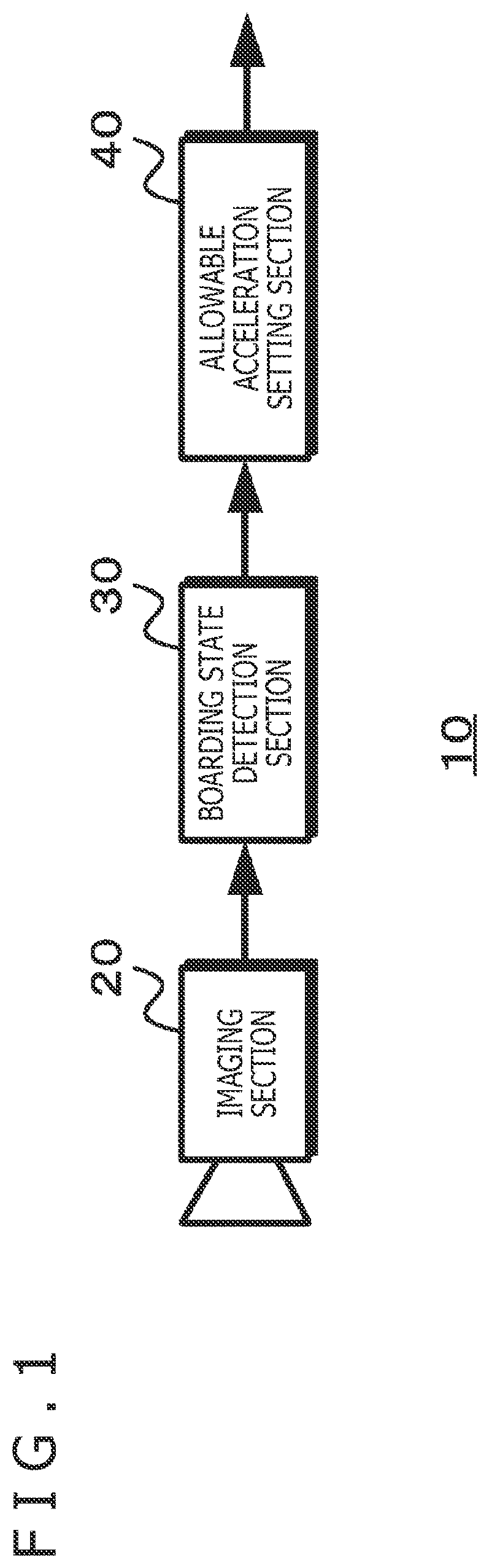
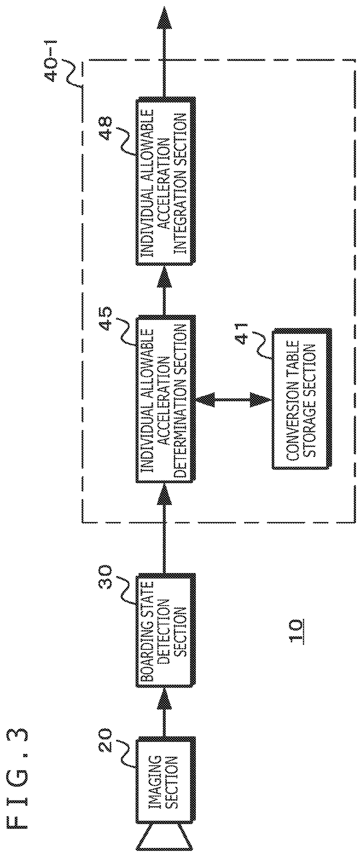
[0050]FIG. 3 illustrates a configuration of a first embodiment of the information processing apparatus. The information processing apparatus 10 includes the imaging section 20, the boarding state detection section 30, and an allowable acceleration setting section 40-1. Further, the allowable acceleration setting section 40-1 includes a conversion table storage section 41, an individual allowable acceleration determination section 45, and an individual allowable acceleration integration section 48.
[0051]The conversion table storage section 41 stores conversion tables indicating the allowable acceleration based on the boarding states. For example, the conversion table storage section 41 stores conversion tables indicating the allowable acceleration corresponding to parameter values, using, as a parameter, the boarding state detected for each passenger by the boarding state detection section 30.
[0052]The individual allowable acceleration determination section 45 deter
second embodiment
1-2. Second Embodiment
[0067]Now, a second embodiment will be described. In the second embodiment, described is a case of detecting, as the boarding state, not only the posture and position but also a surrounding environment state and posture holding state of each passenger, for example, whether the passenger is grabbing the stanchion, the strap, or the like and can hold the posture even in a case where a change in the speed of the moving body or the like occurs.
[0068]FIG. 7 illustrates a configuration of a second embodiment of the information processing apparatus. The information processing apparatus 10 includes the imaging section 20, the boarding state detection section 30, and an allowable acceleration setting section 40-2. Further, the allowable acceleration setting section 40-2 includes the conversion table storage section 41, the individual allowable acceleration determination section 45, an individual allowable acceleration adjustment section 47, and the individual allowable acc
third embodiment
1-3. Third Embodiment
[0082]Now, a third embodiment will be described. In the third embodiment, described is a case of using not only the detection result for the boarding state, but also a temporal change in allowable acceleration.
[0083]FIG. 9 illustrates the configuration of the third embodiment of the information processing apparatus. The information processing apparatus 10 includes the imaging section 20, the boarding state detection section 30, and an allowable acceleration setting section 40-3. Further, the allowable acceleration setting section 40-3 includes the conversion table storage section 41, a state information storage section 42, a conversion table correction section 43, the individual allowable acceleration determination section 45, and the individual allowable acceleration integration section 48.
[0084]The conversion table storage section 41 stores conversion tables indicating allowable acceleration based on the boarding state. For example, stored is the conversion table
PUM
 Abstract
Description
Claims
Application Information
 - R&D Engineer
- R&D Manager
- IP Professional
- Industry Leading Data Capabilities
- Powerful AI technology
- Patent DNA Extraction
Browse by: Latest US Patents, China's latest patents, Technical Efficacy Thesaurus, Application Domain, Technology Topic.
© 2024 PatSnap. All rights reserved.Legal|Privacy policy|Modern Slavery Act Transparency Statement|Sitemap