Replaceable LED bulb with interchageable lens optic

a technology of interchageable lens and led bulb, which is applied in the direction of fixed installation, semiconductor devices for light sources, lighting and heating apparatus, etc., can solve the problems of uncomfortable viewing of led lamps by viewers, and achieve the effects of convenient replacement, good thermal contact, and convenient electrical connection

Inactive Publication Date: 2005-01-25
OSRAM SYLVANIA INC
View PDF17 Cites 100 Cited by
  • Summary
  • Abstract
  • Description
  • Claims
  • Application Information

AI Technical Summary

Benefits of technology

This patent describes a new type of LED lamp used in vehicles. It uses different types of lamps like traditional halogen lights and LED lights. These lamps can be changed without having to throw away them completely. They also use a special kind of reflector called a reflector cup to help it connect properly and create better heat transfer. A cylinders are placed around these lamps to protect them from damage during transportation. Overall, this technology allows for flexibility in designing LED lamps for various purposes such as car headlights.

Problems solved by technology

This patent describes a problem with current designs used for producing standard LED lights for automobiles. These devices require different types of LEDs, making it difficult to create a compact and versatile LED light system for automotive uses. Additionally, existing systems have limitations in providing sufficient spread and focusing of light on the subject area. Therefore, there is a technical problem addressed by this patent.

Method used


Image

  • Replaceable LED bulb with interchageable lens optic
  • Replaceable LED bulb with interchageable lens optic
  • Replaceable LED bulb with interchageable lens optic

Examples


Embodiment Construction

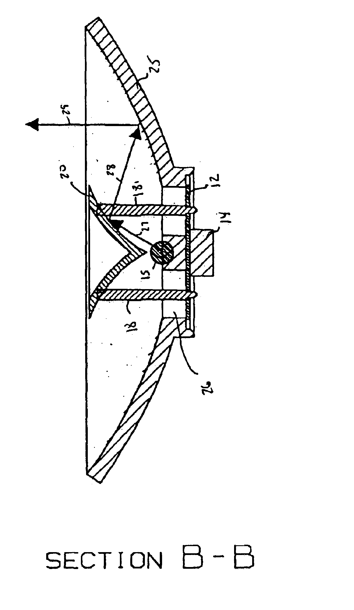
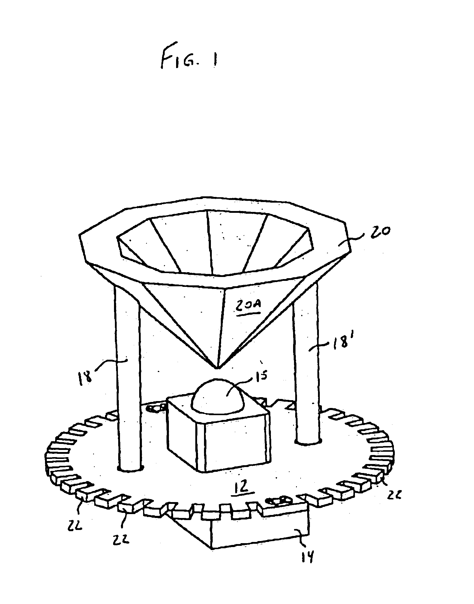
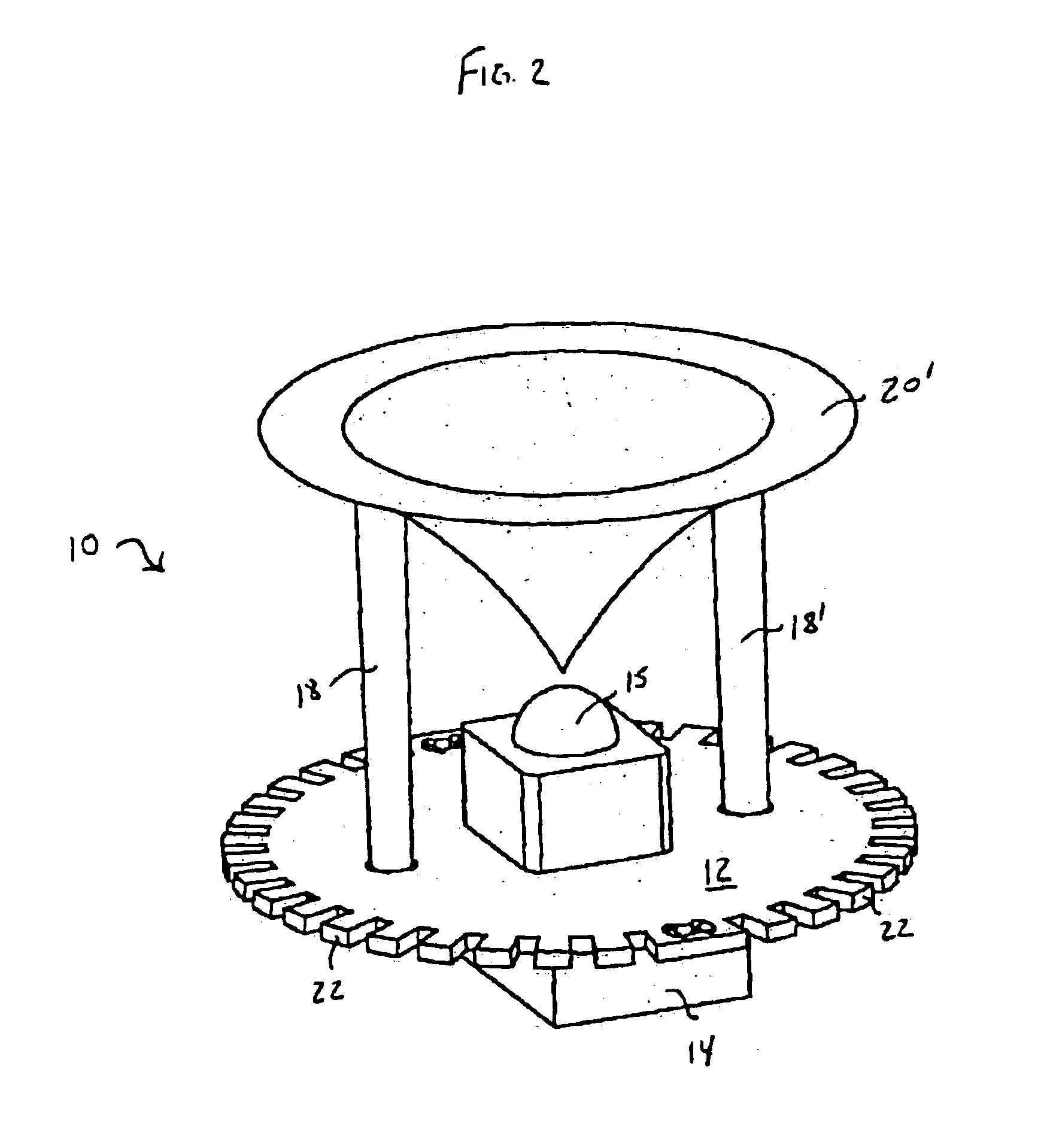
Turning first to FIG. 1, there is shown generally at 10 a lamp assembly in accordance with one embodiment of the present invention. The assembly includes a base plate 12, preferably made of metal so as to act as a heat sink. The base plate 12 can include a plurality of cooling fins 22 formed around its outer perimeter to assist in cooling the assembly. The shape of the cooling fins 22 is not particularly limited; for example, the fins 22 can taper towards their free end, be rounded at their corners, etc. The base plate 12 supports the LED light source or bulb 15 which is mounted to the plate by any suitable means. Positioned below or underneath the base plate 12 is an electric module 14 in electrical communication with the replaceable LED Bulb 15. Positioned above the LED bulb 15 is an optic or intermediate reflector 20. The optic 20 illustrated is a molded and metallized faceted. (depending in part on desired beam spread) optic, having an outer reflective surface 20A facing the light


PUM


Abstract

LED lamp assembly particularly adapted for automotive applications that utilizes one or more standard replaceable LED bulbs with changeable optics to make multiple beam patterns. Preferably the optic is molded and easily replaced. An electric module is mounted directly under the LED to facilitate the electrical connection and provide good thermal contact. The LED light source(s) and interchangeable optic are positioned and sealed in the base of a main reflector or the vehicle hull by means well known to those skilled in the art.

Description


Claims


Application Information

Patent Timeline
Owner OSRAM SYLVANIA INC
Why Eureka
Try Eureka