Clamshell and small volume chamber with fixed substrate support

Inactive Publication Date: 2005-03-15
APPLIED MATERIALS INC
View PDF88 Cites 130 Cited by
  • Summary
  • Abstract
  • Description
  • Claims
  • Application Information

AI Technical Summary

Benefits of technology

Embodiments of the present invention generally relate to a clamshell and small volume chamber with a fixed substrate support. One embodiment of a processing chamber includes a fixed substrate support having a substrate receiving surface, a pumping ring disposed around a perimeter of the substrate receiving su

Problems solved by technology

However, as the fringes of circuit technology are pressed, the shrinking dimensions of interconnects in VLSI and ULSI technology have placed additional demands on the processing capabilities.
Many traditional deposition processes have difficulty filling sub-micron structures where the aspect ratio exceeds 4:1.
Therefore, there is a great amount

Method used


Image

  • Clamshell and small volume chamber with fixed substrate support
  • Clamshell and small volume chamber with fixed substrate support
  • Clamshell and small volume chamber with fixed substrate support

Examples


examples

The following examples will now reveal additional details and features concerning embodiments of the processing chamber. The following examples should not be construed to limit the scope of the invention unless expressly set forth in the claims.

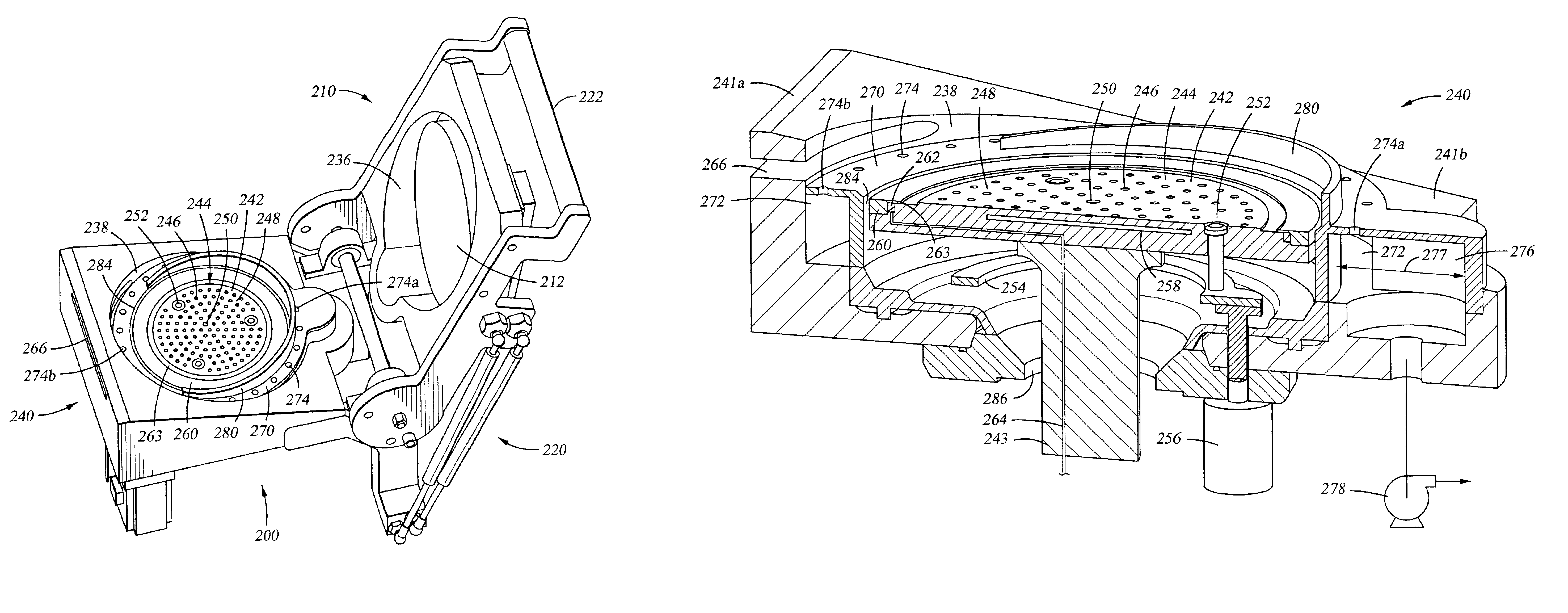
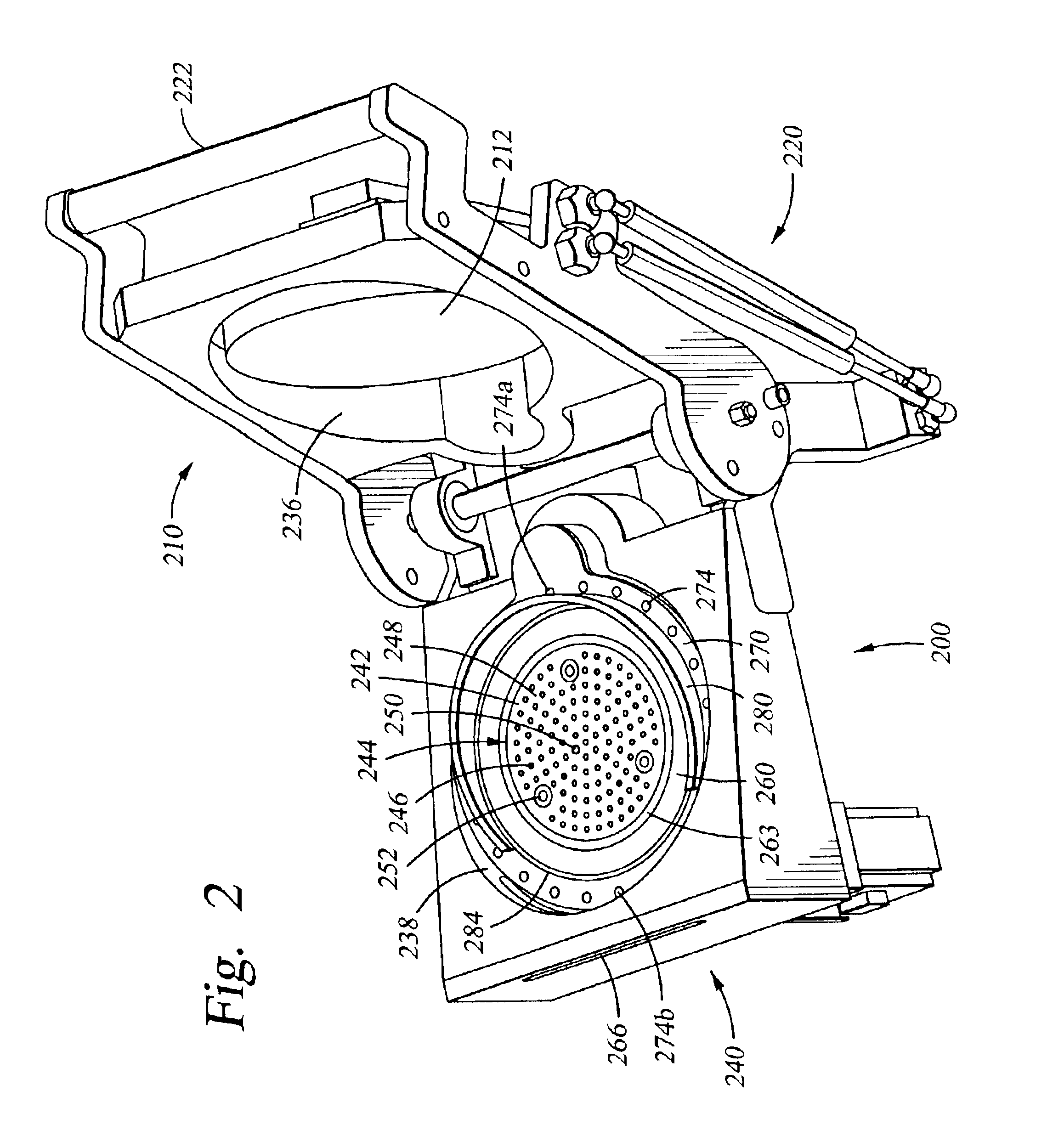
Simulations were conducted of the flow of gases in regards to chambers, such as a chamber described in reference to FIG. 2 and FIG. 4, having gas-flow diffusers of different heights. An uniform top flow of gases was provided to the substrate. Each chamber included a pumping ring having 24 apertures and a gas-flow diffuser extending between about 60% and about 70% around the perimeter of the substrate receiving surface 244. In Example 1, the gas-flow diffuser had a tapered height with a maximum height of about 0.8 inches. In Example 2, the gas-flow diffuser had a tapered height with a maximum height of about 0.7 inches. The simulations estimated the velocity of gases 0.1 inch above a substrate positioned on a substrate support of the chambers. Th


PUM

PropertyMeasurementUnit
Lengthaaaaaaaaaa
Sizeaaaaaaaaaa
Heightaaaaaaaaaa

Abstract

Embodiments of the present invention generally relate to a clamshell and small volume chamber with a fixed substrate support. One embodiment of a processing chamber includes a fixed substrate support having a substrate receiving surface, a pumping ring disposed around a perimeter of the substrate receiving surface, and a gas distribution assembly disposed over the fixed substrate support. The pumping ring forms at least a portion of a pumping channel and has one or more apertures formed therethrough. The chamber may further include a gas-flow diffuser disposed radially inward of the apertures of the pumping ring. Another embodiment of a processing chamber includes a first assembly comprising a fixed substrate support and a second assembly comprising a gas distribution assembly. The first assembly includes a first assembly body that is shaped and sized so that at least a portion of the first assembly body is below the substrate receiving surface of the substrate support. A hinge assembly couples the first assembly and the second assembly. The first assembly and the second assembly can be selectively positioned between an open position and a closed position.

Description


Claims


Application Information

Patent Timeline
Owner APPLIED MATERIALS INC
Why Eureka
Try Eureka