Spark plug connector

a technology of spark plugs and connectors, which is applied in the direction of engine ignition, coupling device connections, other installations, etc., can solve the problems of high heating problems, unnecessarily high quantity of useful energy, and components such as spark plug connectors, and achieves low resistance to the lower-frequency useful energy, improve the energy balance, and reduce the effect of heat loss

Active Publication Date: 2007-08-07
GE JENBACHER
View PDF10 Cites 2 Cited by
  • Summary
  • Abstract
  • Description
  • Claims
  • Application Information

AI Technical Summary

Benefits of technology

The present invention relates to an induction interference suppressing device that uses an inductor instead of an ohmic resistors to improve its energy balance. This helps to reduce interference between different frequency signals without affecting their power levels. It also includes a special type of wound iron core called a magnetically insulating ferrimagnet core (MIF) that allows for better inductance while keeping the size of the device smaller. Additionally, there is a special type of MIF that works well at temperatures below 25°C.

Problems solved by technology

The technical problem addressed in this patent is how to prevent interference caused by the use of excessive amounts of energy during igniting systems like large engines due to the lack of sufficient rigidness needed for easy pushing or adjustment of the spark plug connections.

Method used


Image

  • Spark plug connector
  • Spark plug connector
  • Spark plug connector

Examples


Embodiment Construction

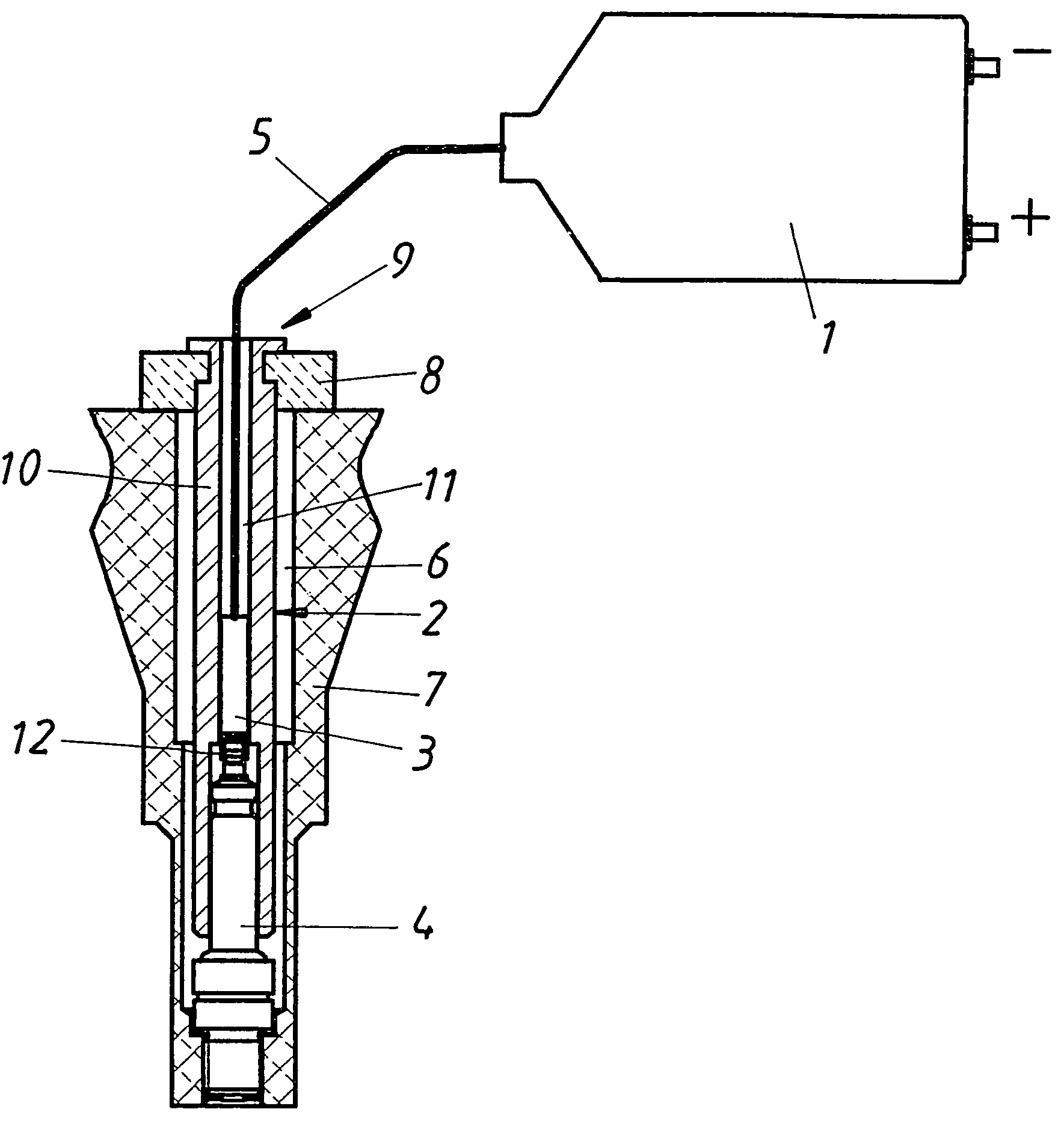
[0013]FIG. 1 shows a structure, in accordance with the invention, in a diagrammatic sectional illustration. The ignition coil 1 is illustrated in a highly simplified manner and may be constructed as known from the prior art. A spark plug lead 5 leads from the ignition coil 1 into the spark plug connector 2, which is arranged in a bore 6 in the engine block 7 and is pushed onto a spark plug 4. Conventionally, there is a plug contact on the end of the spark plug connector 2 remote from the spark plug 4, and the plug contact serves to connect the spark plug 4 to an external spark plug lead cable 5. This detail is not illustrated here, but may be constructed as known from the prior art. Preferably, the spark plug connector is a separate component from the ignition coil 1. As a result of this, unnecessary loads on the ignition coil arising from vibration and heat are avoided, since the ignition coil can be arranged at a remote location, connected to the spark plug connector 2 by way of the


PUM


Abstract

A spark plug connector, in particular for large engines, includes an inductive interference suppression device having a ferromagnetic core. The inductive interference suppression device also has at least one winding, preferably a coil, and an ohmic d.c. resistance of at least 20Ω at 20° C.

Description


Claims


Application Information

Patent Timeline
Owner GE JENBACHER
Why Eureka
Try Eureka