Force-bearing type superposed component for concrete building lid

A superimposed component, load-bearing technology, applied in the direction of structural elements, building components, floors, etc., can solve the problems of poor integrity, high cost, low shear resistance of the superimposed interface, and achieve the effect of good symmetry

Inactive Publication Date: 2008-07-30
邱则有
View PDF1 Cites 2 Cited by
  • Summary
  • Abstract
  • Description
  • Claims
  • Application Information

AI Technical Summary

Problems solved by technology

", in this utility model patent scheme, the floor slab is composed of multiple reinforced concrete prefabricated components, and the two-way structure is formed by forming a criss-cross layout with existing steel bars and reinforced concrete prefabricated components, without the need for on-site formwork. The existing steel bars and the original steel bars of the reinforced concrete prefabricated c

Method used


Image

  • Force-bearing type superposed component for concrete building lid
  • Force-bearing type superposed component for concrete building lid
  • Force-bearing type superposed component for concrete building lid

Examples


Embodiment Construction

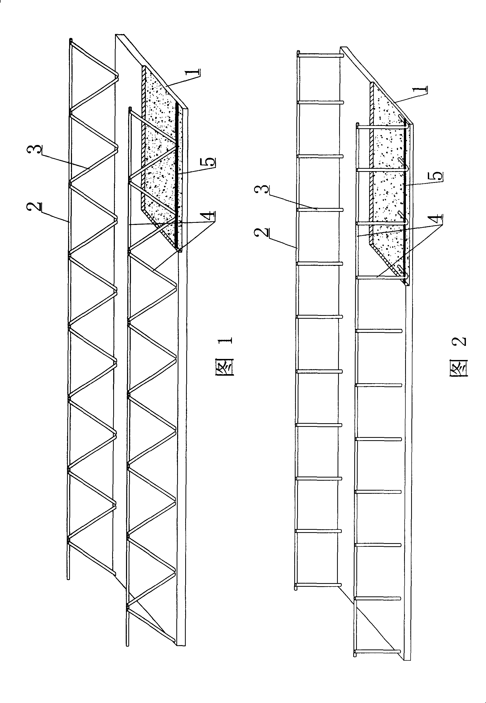
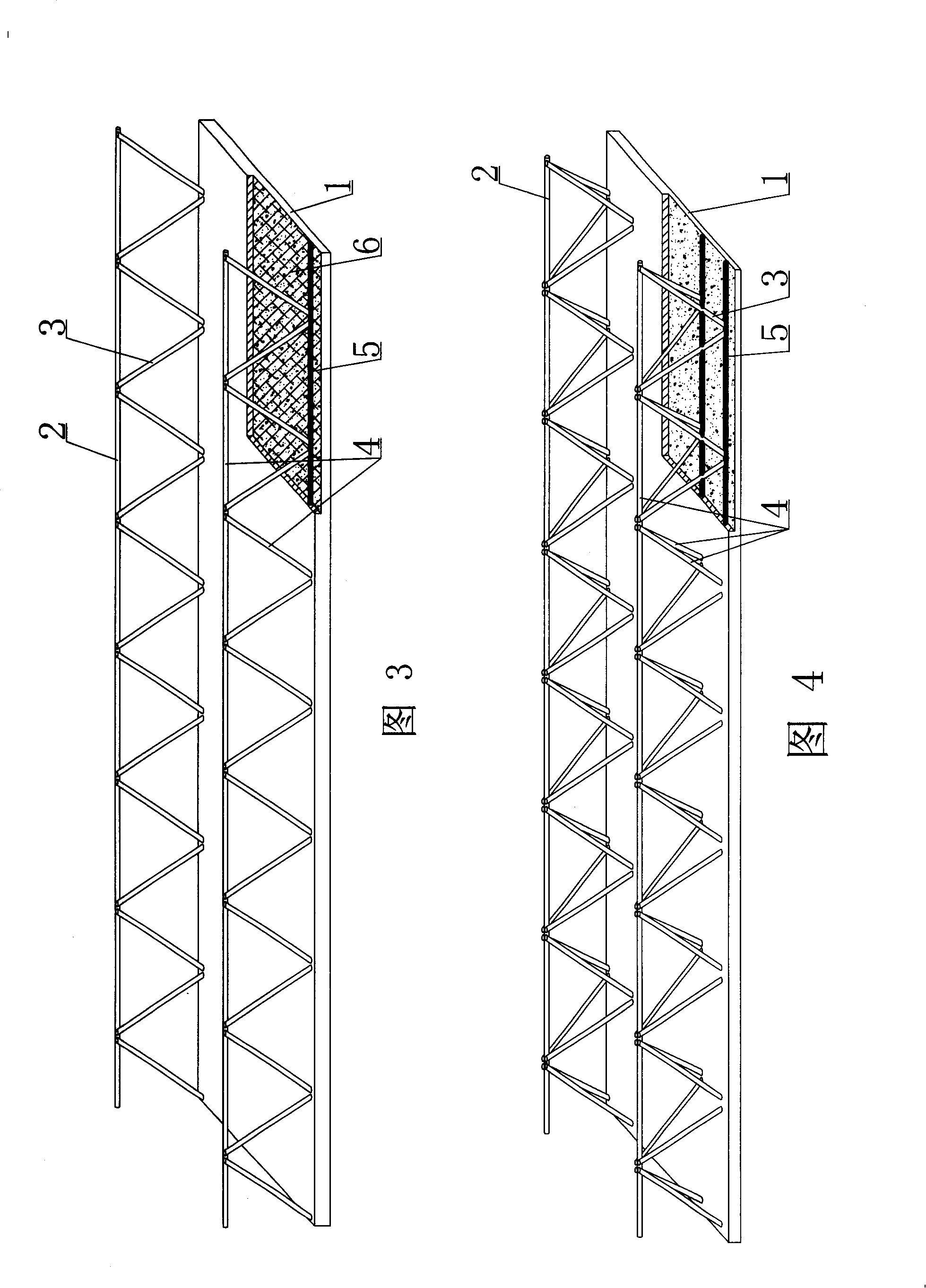
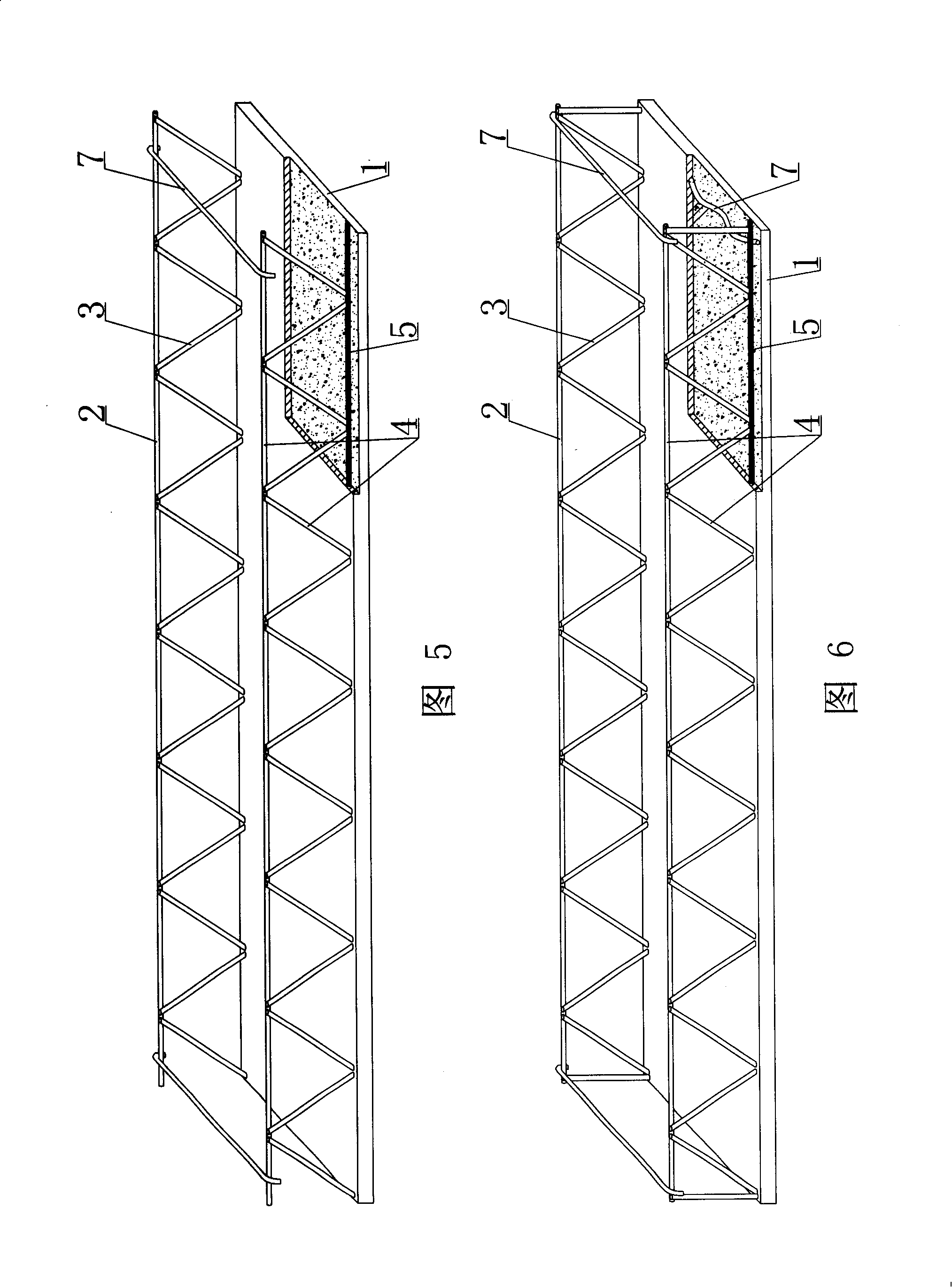
[0052] The present invention will be further described below in conjunction with the accompanying drawings and embodiments.

[0053] As shown in the drawings, the present invention includes a bottom plate 1, which is characterized in that it also includes an upper chord 2 and a web 3, and the upper chord 2 and the bottom plate 1 are connected as a whole by the web 3 to form a space load-bearing member of the bar-plate truss 4 , there is at least one steel bar 5 parallel to the upper chord 2 in the bottom plate 1, and the web bar 3 is connected with the steel bar 5 as a whole. In each accompanying drawing, 1 is the bottom plate, 2 is the upper chord, 3 is the web, 4 is the rod-plate truss, and 5 is the steel bar. In the following drawings, those with the same number have the same description. As shown in FIG. 1 , there is a steel bar 5 parallel to the upper chord 2 inside the bottom plate 1 , and the web bar 3 is connected with the steel bar 5 as a whole.

[0054] The present inv


PUM


Abstract

The invention relates to a structural stressed superposed component used for a concrete floor system, the superposed component is composed of a soleplate (1) and is characterized in that the invention also is provided with a top boom (2) and a web member (3); wherein, the top boom (2) is connected with the template (1) into a whole through the web member (3) thereby forming a force-bearing component of a truss board (4); the soleplate (1) is internally provided with at least a reinforcing steel bar (5) parallel to the top boom (2); the top boom (2) is connected with the reinforcing steel bar (5) into a whole. The invention is applicable to cast-in-situ reinforced concrete or a hollow floor system, a roof system, walls and a foundation slab of the prestressed reinforced concrete as well as a vierendeel bridge girder, and is particularly suitable for a hollow flat slab.

Description


Claims


Application Information

Patent Timeline
Owner 邱则有
Why Eureka
Try Eureka