Aggregate sampling drill

An aggregate and drill bit technology is applied in the field of concrete production equipment, which can solve the problems of unqualified, low material reclaiming efficiency, and lowering concrete, etc., and achieve the effects of large effective capacity, convenient use and high sampling efficiency.

Pending Publication Date: 2022-06-21
重庆茂侨科技有限公司
View PDF0 Cites 0 Cited by
  • Summary
  • Abstract
  • Description
  • Claims
  • Application Information

AI Technical Summary

Problems solved by technology

Inferior fine aggregates will lead to a decrease in the strength and durability of the produced concrete and even unqualified concrete. In order to reduce the quality risk of concrete production enterprises, it is necessary to increase the sampling and testing frequency of fine aggregates entering the site.
[0003] At present, the drill bit of the sampl

Method used


Image

  • Aggregate sampling drill
  • Aggregate sampling drill
  • Aggregate sampling drill

Examples


Embodiment Construction

[0034] In order to enable those skilled in the art to better understand the present invention, the technical solutions of the present invention are further described below with reference to the accompanying drawings and embodiments.

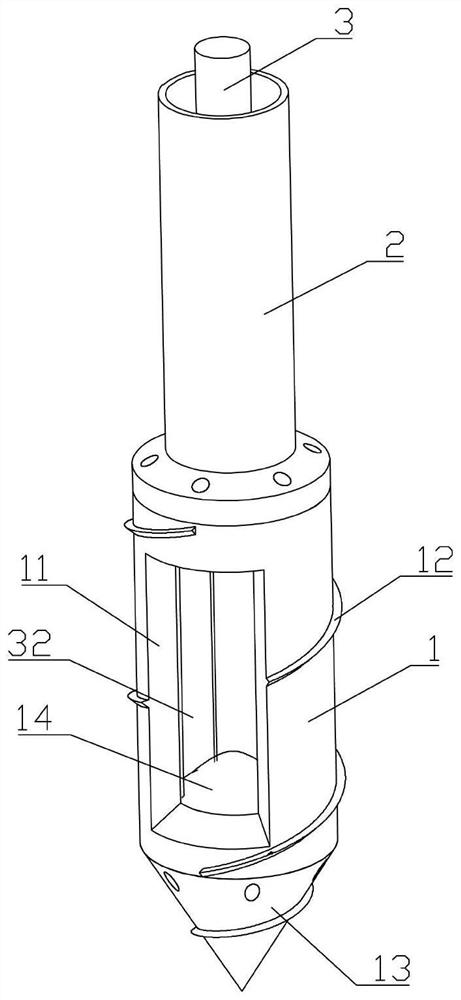
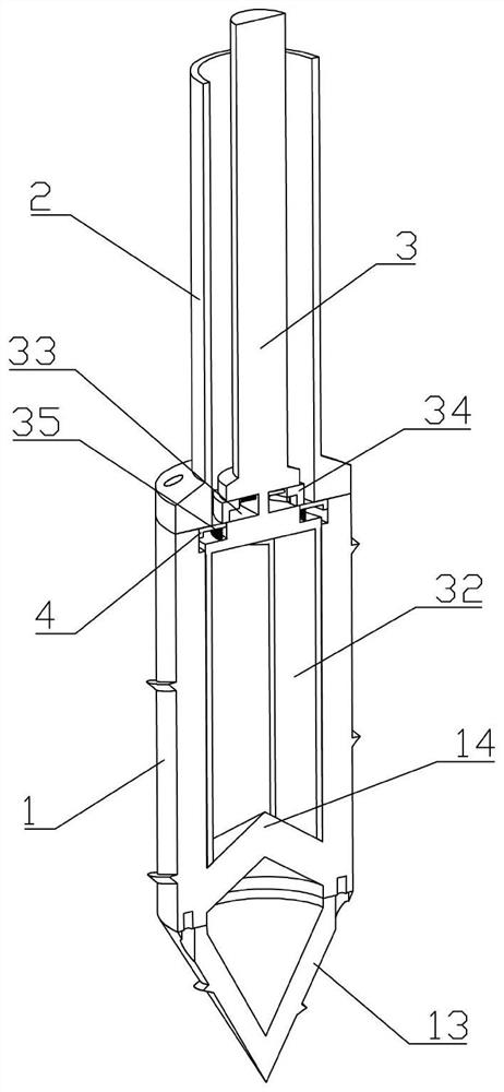
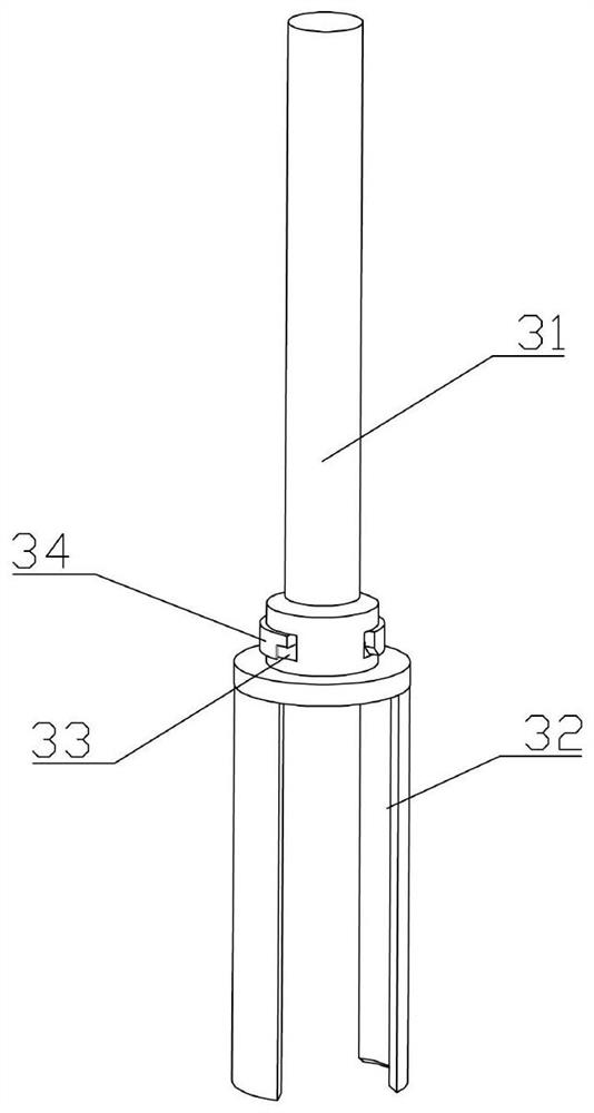
[0035] like Figures 1 to 3 As shown, an aggregate sampling drill includes a cylinder body 1 and a connection cylinder 2 that are fixedly connected. The cylinder body 1 is provided with a spiral convex strip 12. A drill bit 13 is fixedly installed at the bottom end of the body 1. The drill bit 13 is a hollow structure, which is beneficial to reduce the overall weight of the sampling drill. The cylinder body 1 is provided with a feeding port 11, and a closure member 3 is installed in the cylinder body 1. The closure member 3 includes The transmission rod 31 and the sealing plate 32 are fixedly connected. After the sealing plate 32 is opened, the aggregate can enter the cylinder 1 along the feeding port 11. After the sealing plate 32 closes the feedin


PUM


Abstract

The invention belongs to the technical field of concrete production equipment, and particularly relates to an aggregate sampling drill which comprises a barrel and a connecting barrel which are fixedly connected, a drill bit is fixedly mounted at the bottom end of the barrel, a feeding port is formed in the barrel, a sealing part is mounted in the barrel and comprises a transmission rod and a sealing plate which are fixedly connected, and the transmission rod is fixedly connected with the connecting barrel. A cone is arranged at the inner bottom of the barrel, a spiral protruding strip is arranged on the barrel, the drill bit is of a hollow structure, and the aggregate sampling drill is used for solving the problems that an existing aggregate sampling drill is low in material taking efficiency and small in effective capacity.

Description


Claims


Application Information

Patent Timeline
Owner 重庆茂侨科技有限公司
Why Eureka
Try Eureka