Electronic device installed in an engine room

A technology for engine rooms and electronic equipment, applied to circuits, printed circuits, electrical components, etc., can solve problems without any consideration, and achieve the effect of increasing the service life, extending the connection life, and prolonging the service life

Inactive Publication Date: 2008-08-20
HITACHI LTD
View PDF1 Cites 1 Cited by
  • Summary
  • Abstract
  • Description
  • Claims
  • Application Information

AI Technical Summary

Benefits of technology

This patented technology prevents damage caused during mounting electronics components onto printed wiring boards (PWBs). By covering only certain areas where connections occur through the PWB' s own metallic layer instead of other regions containing copper, this reduces the risk for electrical short circuits between adjacent pins while maintaining good mechanical strength and long-term reliance upon these devices. Additionally, when there is no rustiness inside the cabin due to moisture condensation, the use of special coatings like molybdenum sulfate improves its effectiveness against corrosion without reducing their ability to connect properly. Overall, this technology enhances the longevity and performance of electronic component installations such as those found within engines.

Problems solved by technology

Technological Problem: Existing methods for mounting electronics devices onto printed circuits involve attaching them directly to the outside of the insulating case during manufacture processes. These techniques result in poor mechanical stability when subjected to severe environmental conditions including harsh atmospheric pressure fluctuations over several hundred hours. Additionally, current solutions involving applying a silica adhesives suffer issues related to long term resistance and reduced chemical receptivity compared to pure platinum wire connections.

Method used


Image

  • Electronic device installed in an engine room
  • Electronic device installed in an engine room
  • Electronic device installed in an engine room

Examples


Embodiment Construction

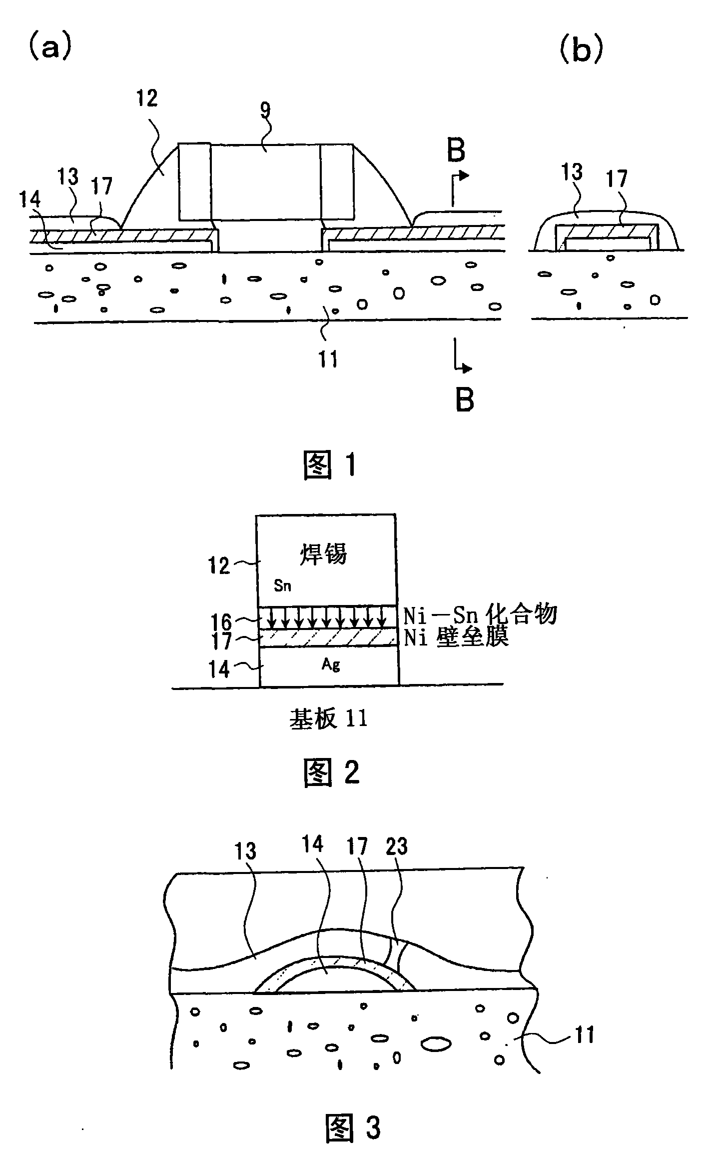
[0055] The main part of the electronic equipment installed in the engine room of this invention is demonstrated based on drawing. FIG. 1 is an enlarged view of a main part of this embodiment, and FIG. 2 is a schematic diagram showing the principle of extending the connection life by soldering of electronic equipment.

[0056] On the surface of the ceramic substrate 11, silver is printed, transferred, or plated to form a conductor pattern from the silver conductor wiring (conductor member) 14, and the entire surface of the conductor wiring 14 is formed by interdiffusion with solder. Nickel, which is a metal member other than the conductor wiring 14 , forms a barrier metal film 17 to cover the periphery of the conductor wiring 14 . Then, after coating the solder 12 on the barrier metal film 17, the chip component 9, which is an electronic component, is mounted, passed through a curing furnace (reflow furnace), thereby melting the solder 12, and connecting the chip component 9 to th


PUM

PropertyMeasurementUnit
Film thicknessaaaaaaaaaa

Abstract

According to the present invention an electronic device, which is to be installed in an engine room, comprises a circuit board 11, electronic elements, which are carried by the circuit board 11 and function when electricity is applied from the circuit board 11 to them, a case 3 that accommodates the circuit board 11 on which the electronic elements are disposed, and a cover 6 that covers an opening of the case 3, the entire surface of a conductor pattern formed of a conductive material on the circuit board is covered with a barrier metallic film made of a metal other than the metal of the conductive material having a property of mutual diffusion with a solder material, and the barrier metallic film is further covered with a protective insulating film.

Description


Claims


Application Information

Patent Timeline
Owner HITACHI LTD
Why Eureka
Try Eureka