Slurry bed ft synthetic reactor and technique
A technology of Fischer-Tropsch synthesis and reactors, applied in chemical instruments and methods, chemical/physical processes, etc.
- Summary
- Abstract
- Description
- Claims
- Application Information
AI Technical Summary
Problems solved by technology
Method used
Image

Examples
Embodiment 1
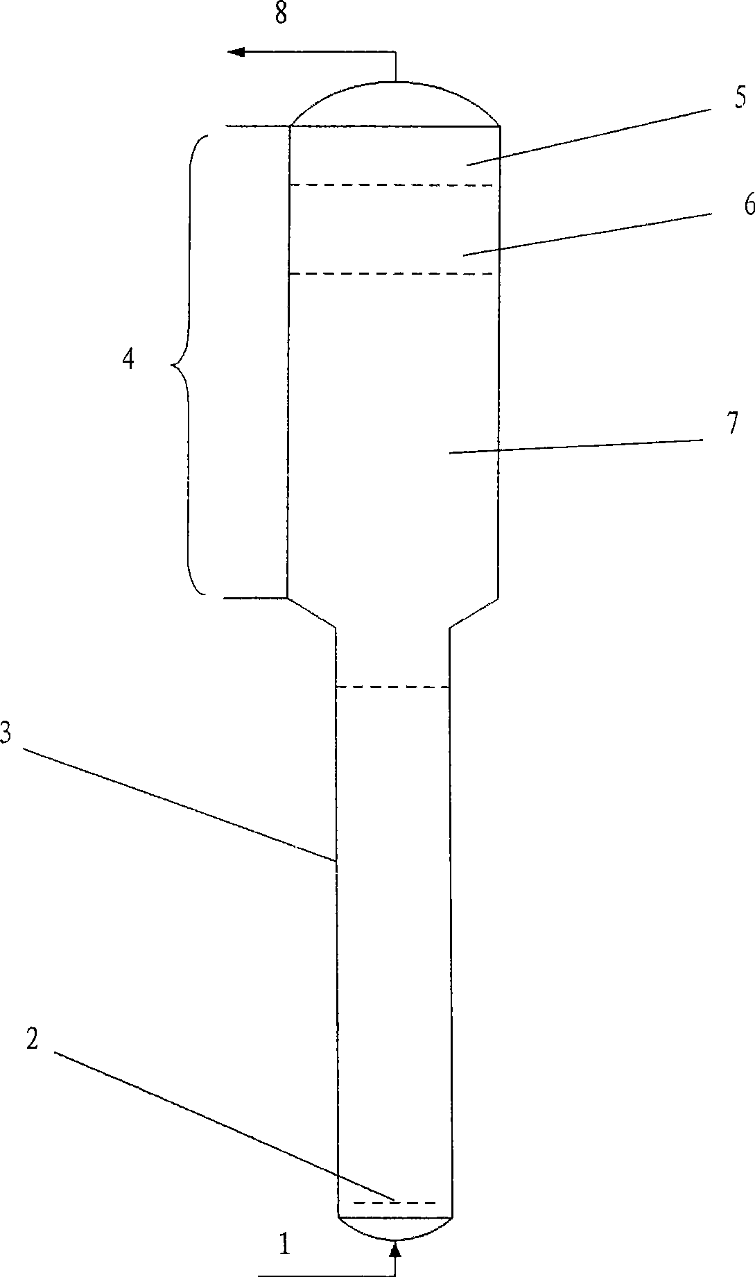
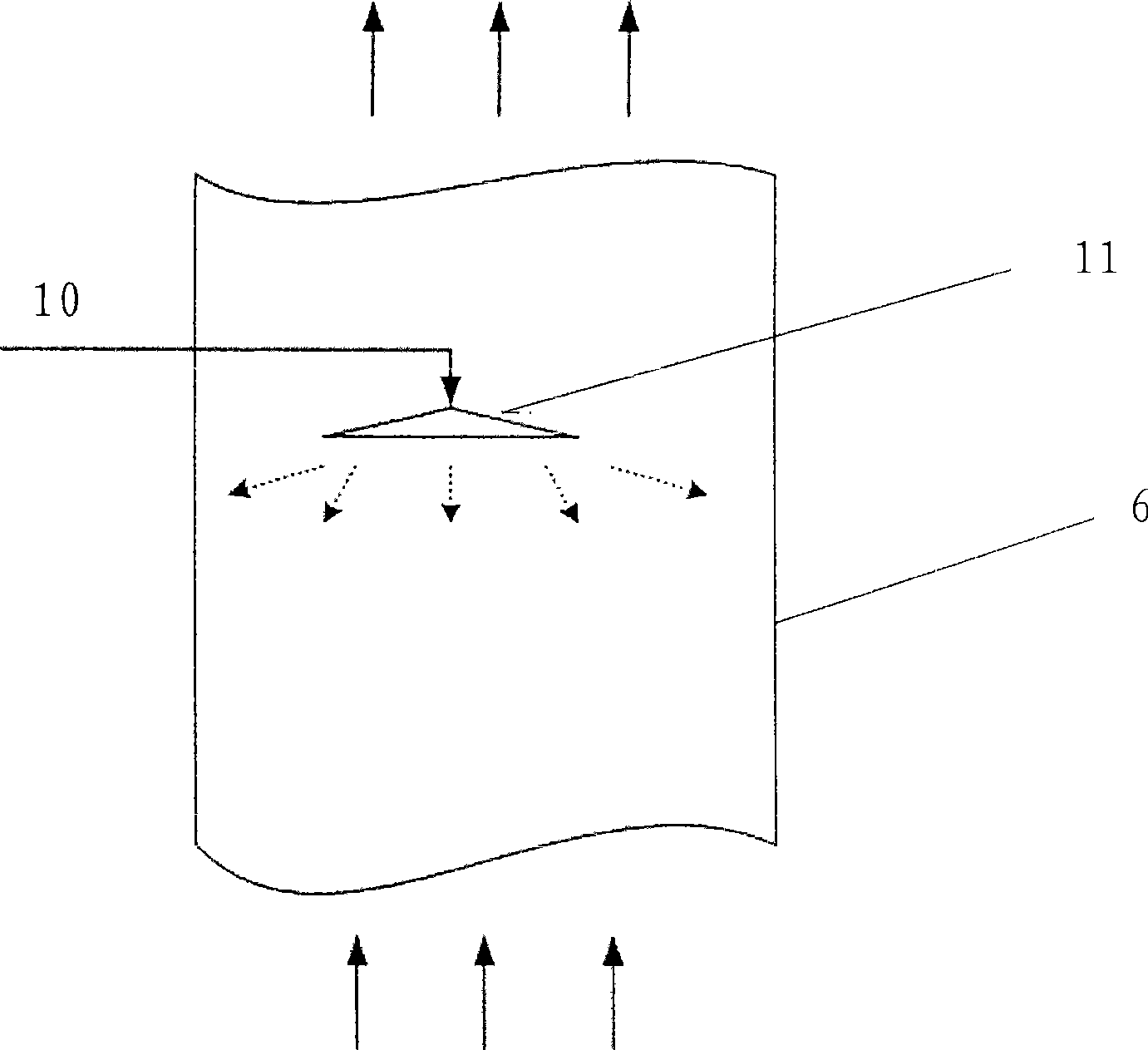
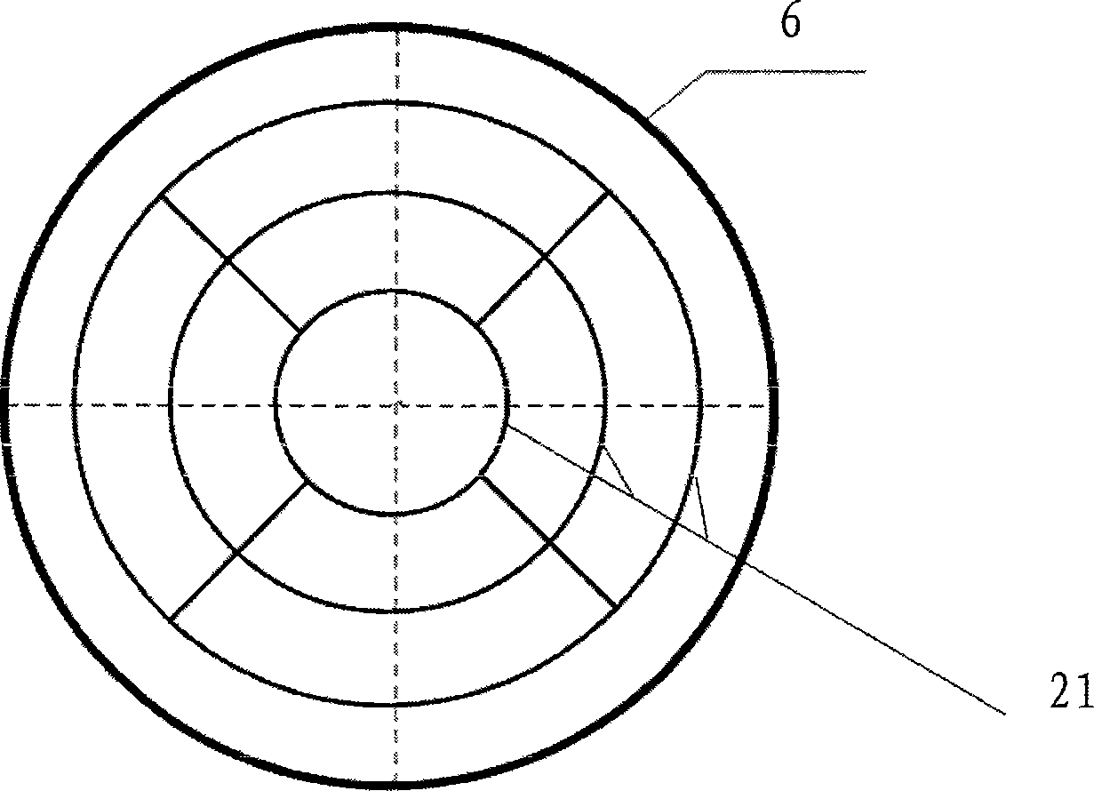
[0020] The inner diameter of the slurry bed is 5m, the total height of the reaction section and the gas distributor section is 30m, the inner diameter of the expansion section is 7m, the height of the gravity settling section is 8m, the height of the defoaming section is 0.6m, and enters the reactor washing section The pressure of the gas phase is 2.9Mpa, the temperature is 240°C, and the flow rate is 200 tons / hour. The quality of the washing liquid entering from the outside of the slurry bed is 2% of the mass flow rate of the gas phase, the temperature is 235 ° C, and the pressure is 3.2 Mpa. It is sprayed downward from the liquid distributor on the upper part of the washing section to contact the gas phase. By adjusting the pressure of the washing liquid, that is, the pressure difference between the inlet and outlet of the liquid distributor (spray ring), the size of the spray droplets can be adjusted, and the droplets can best separate fine particles between 200-600 microns.
Embodiment 2
[0023]The inner diameter of the slurry bed is 5m, the inner diameter of the expansion section is 7m, the height of the gravity settling section is 8m, the height of the defoaming section is 0.6m, the pressure of the gas phase entering the reactor washing section is 2.9Mpa, the temperature is 240°C, and the flow rate is 200 tons / hour. The mass of the washing liquid entering from the slurry bed is 4% of the mass flow rate of the gas phase, the temperature is 230°C, and the pressure is 3.0Mpa. After the washing liquid enters the reactor, it flows down through the overflow weir, downcomer and sieve, and contacts with the gas phase to remove fine particles. The washing section is equipped with 4 layers of sieve plates, the distance between the sieve plates is 300mm, the opening diameter of the sieve plate is 10mm, the sieve holes are arranged in an equilateral triangle, the hole spacing is 30mm, and the opening rate is 9.5%. 5mm, the distance between the lower end of the downcomer
PUM
 Abstract
Description
Claims
Application Information
 - R&D Engineer
- R&D Manager
- IP Professional
- Industry Leading Data Capabilities
- Powerful AI technology
- Patent DNA Extraction
Browse by: Latest US Patents, China's latest patents, Technical Efficacy Thesaurus, Application Domain, Technology Topic.
© 2024 PatSnap. All rights reserved.Legal|Privacy policy|Modern Slavery Act Transparency Statement|Sitemap