Method for removing acid gas in fume gas using a spray tower
An acid gas, spray tower technology, applied in separation methods, chemical instruments and methods, dispersed particle separation, etc., can solve problems such as increased power consumption, system shutdown, scaling, etc., to reduce blockage and improve utilization. , to achieve the effect of reuse
- Summary
- Abstract
- Description
- Claims
- Application Information
AI Technical Summary
Problems solved by technology
Method used
Image

Examples
Embodiment 1
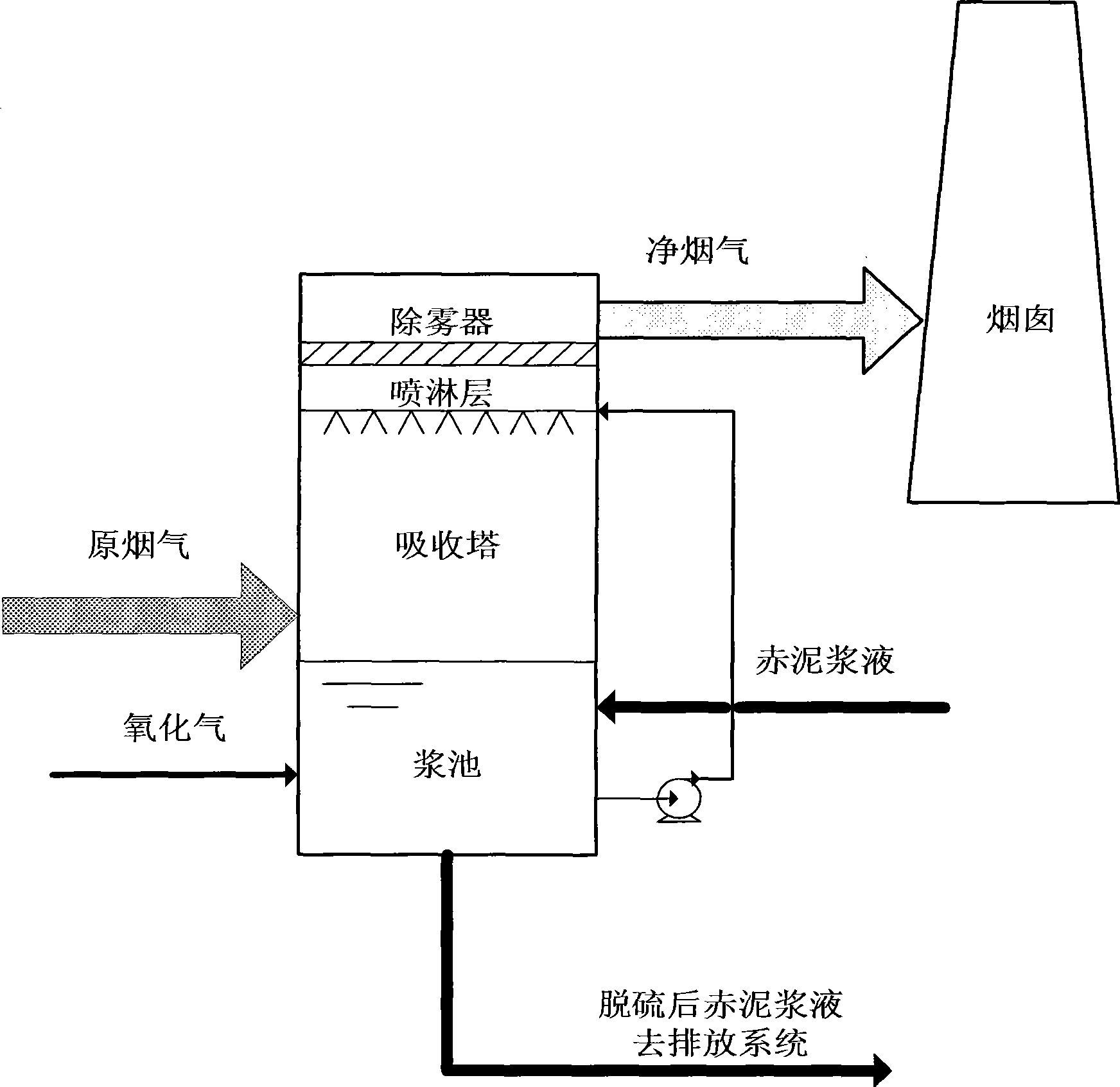
[0028] The solid content of the red mud slurry entering the absorption tower is adjusted to 15%. Under the action of the circulating pump, the absorption slurry is sprayed out from the spray device at the upper part of the spray tower in a mist form, and fully countercurrently contacts the flue gas entering from the middle of the tower. , the control liquid-gas ratio is 9.0, and the pH value of the absorption slurry is 6.0. SO in flue gas 2 After chemical reaction with red mud slurry and blown oxidized air, SO in flue gas 2 is removed. The desulfurized flue gas is discharged into the chimney after removing the fine droplets brought out by the mist eliminator, and the by-product red mud after desulfurization is pumped out of the absorption system. The concentration of the slurry in the absorption tower was controlled to be 20%, and the residence time of the slurry was 7 hours. absorption tower inlet SO 2 The content is 4387mg / Nm 3 , the export content is 573mg / Nm 3 , the
Embodiment 2
[0030] The solid content of the red mud slurry entering the absorption tower is adjusted to 20%. Under the action of the circulating pump, the absorption slurry is sprayed out from the spray device at the upper part of the spray tower in the form of a mist, and fully countercurrently contacts the flue gas entering from the middle of the tower. , the control liquid-gas ratio is 8.0, and the pH value of the absorption slurry is 7.0. SO in flue gas 2 After chemical reaction with red mud slurry and blown oxidized air, SO in flue gas 2 is removed. The desulfurized flue gas is discharged into the chimney after removing the fine droplets brought out by the mist eliminator, and the by-product red mud after desulfurization is pumped out of the absorption system. The concentration of the slurry in the control absorption tower was 25%, and the residence time of the slurry was 8 hours. absorption tower inlet SO 2 The content is 4622mg / Nm 3 , the export content is 413mg / Nm 3 , the d
Embodiment 3
[0032] The solid content of the red mud slurry entering the absorption tower is adjusted to 25%. Under the action of the circulating pump, the absorption slurry is sprayed from the spray device at the upper part of the spray tower in a mist form, and fully countercurrently contacts the flue gas entering from the middle of the tower. , the control liquid-gas ratio is 7.0, and the pH value of the absorption slurry is 8.0. SO in flue gas 2 After chemical reaction with red mud slurry and blown oxidized air, SO in flue gas 2 is removed. The desulfurized flue gas is discharged into the chimney after removing the fine droplets brought out by the mist eliminator, and the by-product red mud after desulfurization is pumped out of the absorption system. The concentration of the slurry in the absorption tower was controlled to be 30%, and the residence time of the slurry was 8 hours. absorption tower inlet SO 2 The content is 5120mg / Nm 3 , the export content is 389mg / Nm 3 , the des
PUM
 Abstract
Description
Claims
Application Information
 - R&D Engineer
- R&D Manager
- IP Professional
- Industry Leading Data Capabilities
- Powerful AI technology
- Patent DNA Extraction
Browse by: Latest US Patents, China's latest patents, Technical Efficacy Thesaurus, Application Domain, Technology Topic.
© 2024 PatSnap. All rights reserved.Legal|Privacy policy|Modern Slavery Act Transparency Statement|Sitemap