Energy-saving device of wet desulphurization spray tower

A technology of wet desulfurization and energy-saving devices, applied in separation methods, chemical instruments and methods, gas treatment, etc., can solve the problems of increasing flue gas resistance, not simple enough structure, increasing energy consumption of desulfurization fans, etc., to reduce flue gas resistance Effect

Pending Publication Date: 2020-10-13
浙江菲达环保科技股份有限公司
View PDF1 Cites 0 Cited by
  • Summary
  • Abstract
  • Description
  • Claims
  • Application Information

AI Technical Summary

Problems solved by technology

The "waterfall" absorbing liquid will block the flue gas entering the spray tower, increase the resistance of the flue gas, and thus increase the energy consumption of the desulfurization fan
On the other hand, the "waterfall" will lead to the accumulation of solids in the flue gas inlet flue, increasing the resistance of the flue gas, thereby increasing the energy consumption of the desulfurization fan
[0004] In order to overcome the above problems, the patent of China Authorized Notification No. CN 208260533 U discloses a wet desulfurization tower inlet device. Although the device reduces energy consumption to a certain extent, there are still some shortcomings, such as the structure is not simple enough There are many tie rods between the side plate of the groove an

Method used


Image

  • Energy-saving device of wet desulphurization spray tower
  • Energy-saving device of wet desulphurization spray tower
  • Energy-saving device of wet desulphurization spray tower

Examples


Embodiment Construction

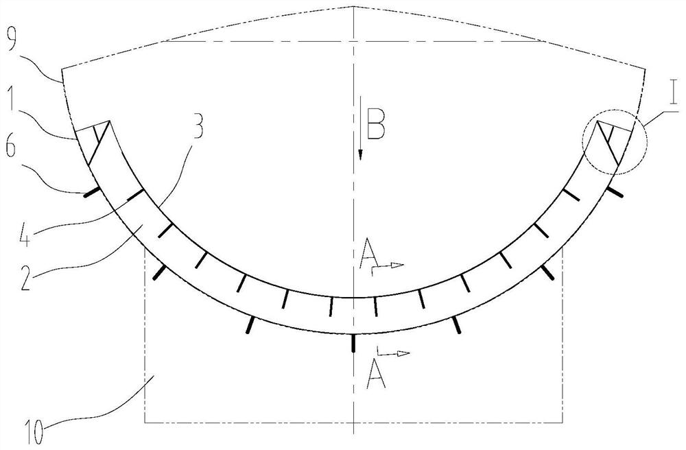
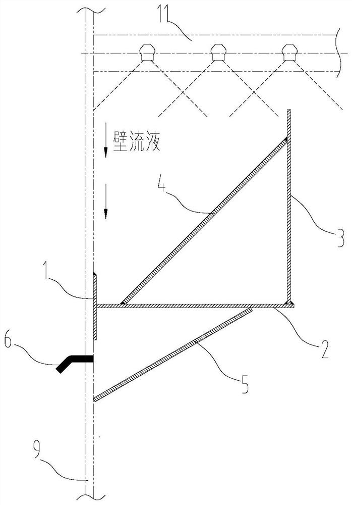
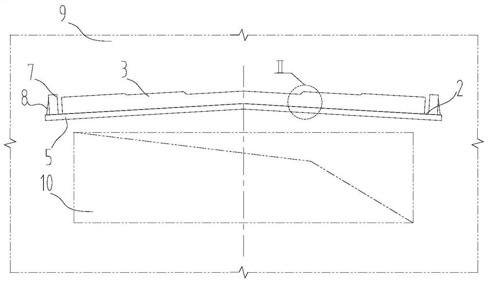
[0023] refer to Figure 1 to Figure 5 An energy-saving device for a wet desulfurization spray tower according to the present invention is installed on the tower wall 9 of the wet desulfurization spray tower between the entrance 10 of the wet desulfurization spray tower and the lowest spray layer 11, including 9 reinforcing plate 1 on the inner side, base plate 2 connected with reinforcing plate 1, side plate 3 installed on the inner side of base plate 2, pull rod 4, sealing plate 5, ventilation pipe 6 and deflector 7, said side plate 3 and At least two tie rods 4 are arranged between the bottom plates 2, and the two ends of the tie rods 4 are respectively connected with the inner wall of the side plate 3 and the upper wall of the bottom plate 2, and an inclined setting is welded between the lower bottom surface of the bottom plate 2 and the tower wall 9. The sealing plate 5 is used to support the bottom plate 2, the side plate 3, the pull rod 4 and the collected wall liquid; at t


PUM


Abstract

The invention provides an energy-saving device of a wet desulphurization spray tower. The device is arranged on the tower wall of the wet desulphurization spray tower between an inlet of the wet desulphurization spray tower and a lowermost spray layer. The energy-saving device comprises a reinforcing plate fixed on the inner side of the tower wall, a bottom plate connected with the reinforcing plate, a side plate installed on the inner side of the bottom plate, pull rods, a sealing plate, vent pipes and flow guide plates; at least two pull rods are arranged between the side plate and the bottom plate; two ends of each pull rod are respectively connected with the inner wall of the side plate and the upper wall of the bottom plate; the inclined sealing plate is welded between the lower bottom surface of the bottom plate and the tower wall; at least two vent pipes are arranged on the tower wall below the bottom plate; the flow guide plates are arranged at two ends of the bottom plate; oneend of each flow guide plate is connected with the reinforcing plate, and a liquid discharge outlet is formed between the other end of each flow guide plate and the side plate. With the device adopted, the problem of accumulation of solids at the inlet of the tower can be effectively solved, a waterfall phenomenon can be avoided, flue gas resistance can be reduced, and energy conservation can berealized.

Description


Claims


Application Information

Patent Timeline
Owner 浙江菲达环保科技股份有限公司
Why Eureka
Try Eureka