Method for executing programmable logic controller (PLC) code

An execution method and machine code technology are applied in the field of PLC machine code execution to achieve the effects of improving responsiveness, simple hardware architecture and software process design, and low cost.

Inactive Publication Date: 2009-11-11
LNC TECH CO LTD
View PDF0 Cites 8 Cited by
  • Summary
  • Abstract
  • Description
  • Claims
  • Application Information

AI Technical Summary

Benefits of technology

This technology allows for faster processing times while still being able to execute programs on different machines that are connected together over an interconnected network like Ethernet or LAN (Local Area Network). It also improves how data travels between these devices efficiently without slowing down any further processes. Overall, this new approach makes programming more efficient and effective at all levels of operation.

Problems solved by technology

The technical problem addressed in this patented technology relates to improving the performance of an electronic device called a programmable logic controlling system used for automated machinery or production lines without sacrificing its functionality.

Method used


Image

  • Method for executing programmable logic controller (PLC) code
  • Method for executing programmable logic controller (PLC) code
  • Method for executing programmable logic controller (PLC) code

Examples


Embodiment Construction

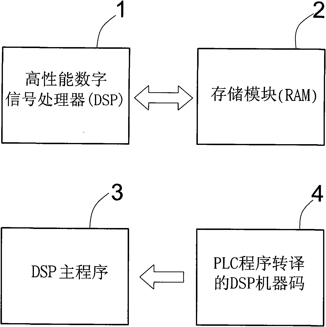
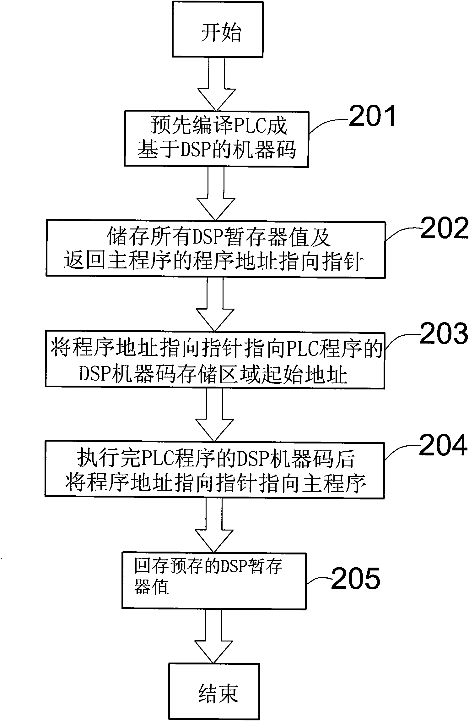
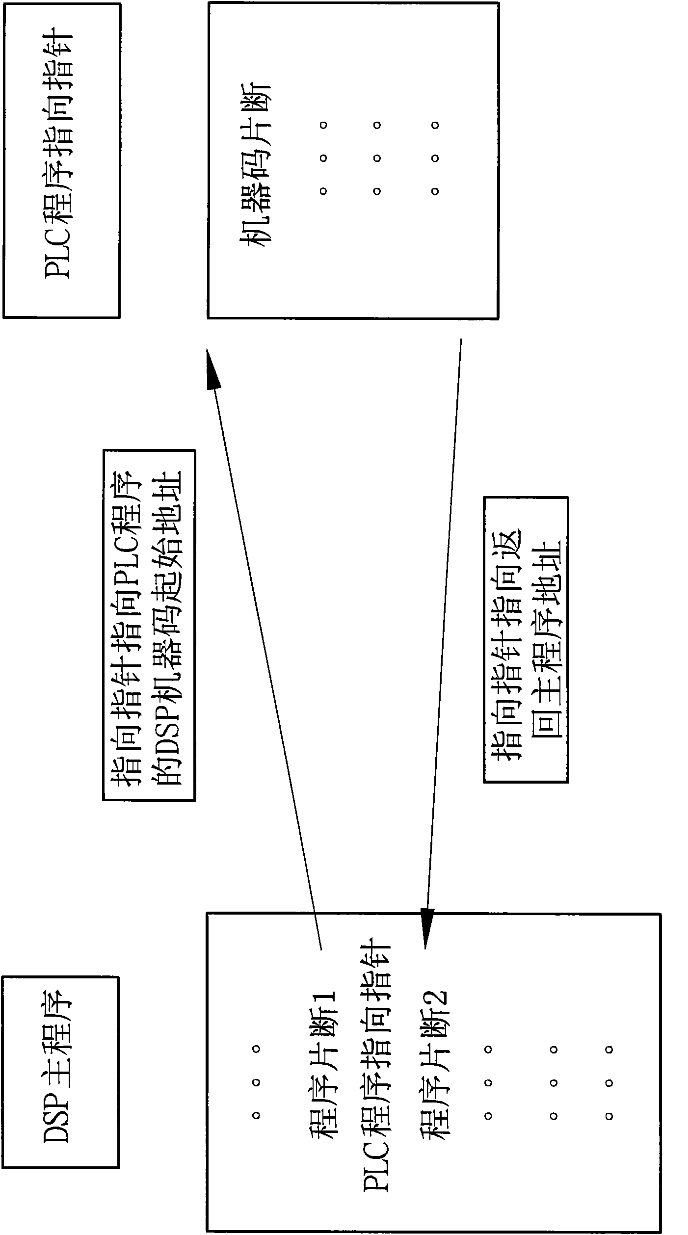
[0014] see figure 1 , which is a system architecture diagram of a PLC machine code execution method of the present invention, its hardware architecture includes at least one high-performance digital signal processor (1) and a storage module (2), wherein the high-performance digital signal processor (1) ) can also be a microprocessor (MCU), and the storage module (2) can be an external memory or a built-in memory of the processor; and the software part includes at least one DSP main program (3) and a PLC program translation DSP machine code (4); the present invention is to develop a program pointing method, first translate the PLC program into DSP machine code, and include it in the DSP main program, so that the cycle scanning time of PLC will not be limited The transmission speed of the communication interface will greatly improve the responsiveness of the system. In particular, the translation of PLC programs into DSP machine codes can be done in advance before program executio


PUM


Abstract

The invention relates to a method for executing a programmable logic controller (PLC) code. The hardware of a PLC comprises at least one high-performance Digital Signal Processing (DSP) and a RAM of a memory module. A software part comprises at least one main program applied to the DSP and a program translated DSP code of the PLC of a cycle ladder diagram. The invention translates a PLC program into the DSP code and executes the PLC code in the DSP. The PLC code is coated in the main program of the DSP so that the cycle scanning time of the PLC is not limited by the transmission speed of a communication interface, thereby the response ability of a system can be effectively improved.

Description


Claims


Application Information

Patent Timeline
Owner LNC TECH CO LTD
Why Eureka
Try Eureka