Robot system

Active Publication Date: 2021-02-25
FANUC LTD
View PDF0 Cites 0 Cited by
  • Summary
  • Abstract
  • Description
  • Claims
  • Application Information

AI Technical Summary

Benefits of technology

[0005]According to an aspect of the present disclosure, there is provided a robot system including: a robot including a plurality of drive shafts; and a control device configured to control the robot, in which each of the drive shafts includes a drive unit configured to cause a second member to operate with respect to a first member, the drive unit includes a motor, a deceleration mechanism configured to decelerate rotation of the motor and supply the rotation to the first member and the second member, and an input-si

Problems solved by technology

In a case in which an encoder attached to the motor is used to detect a rotation angle to control the position of the output shaft, positional devi

Method used


Image

  • Robot system
  • Robot system
  • Robot system

Examples


Embodiment Construction

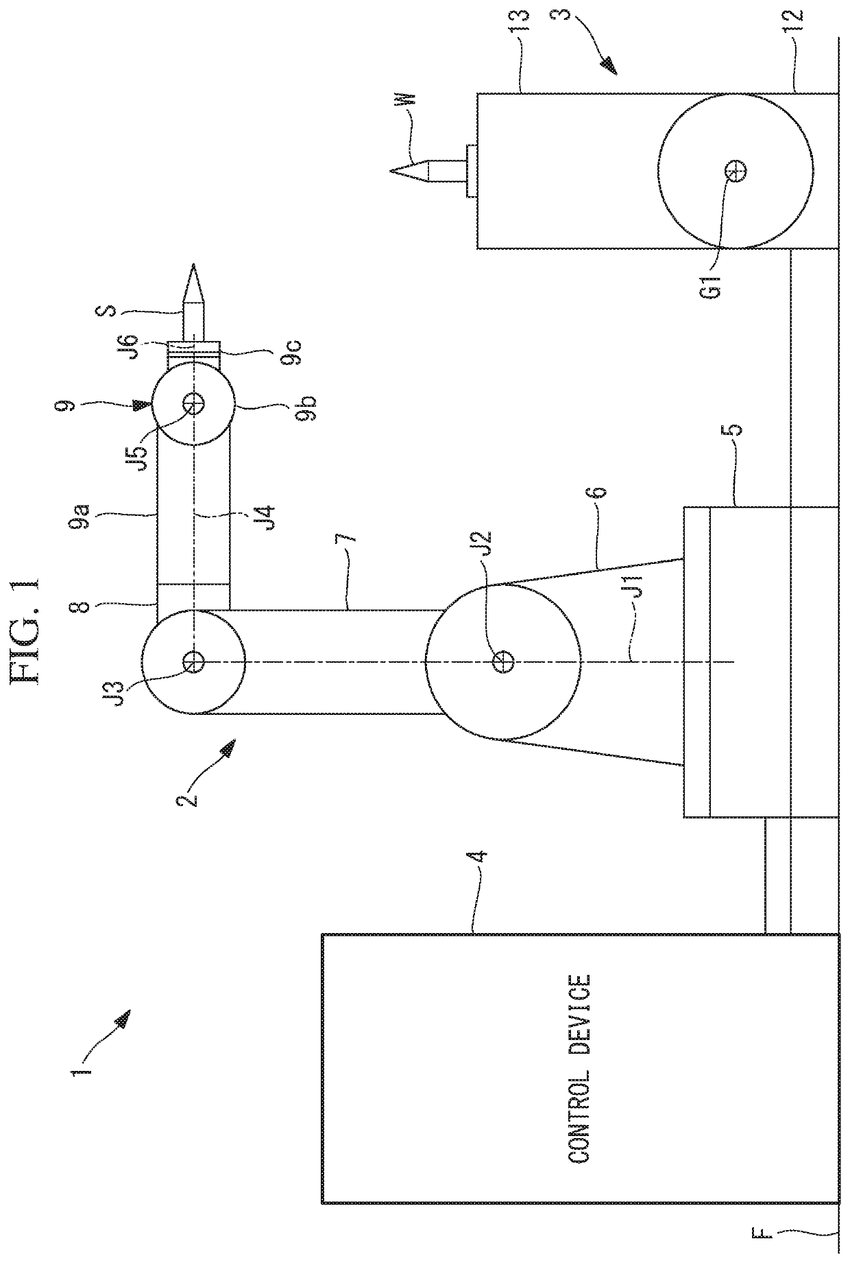
[0012]A robot system 1 according to an embodiment of the present disclosure will be described below with reference to drawings.

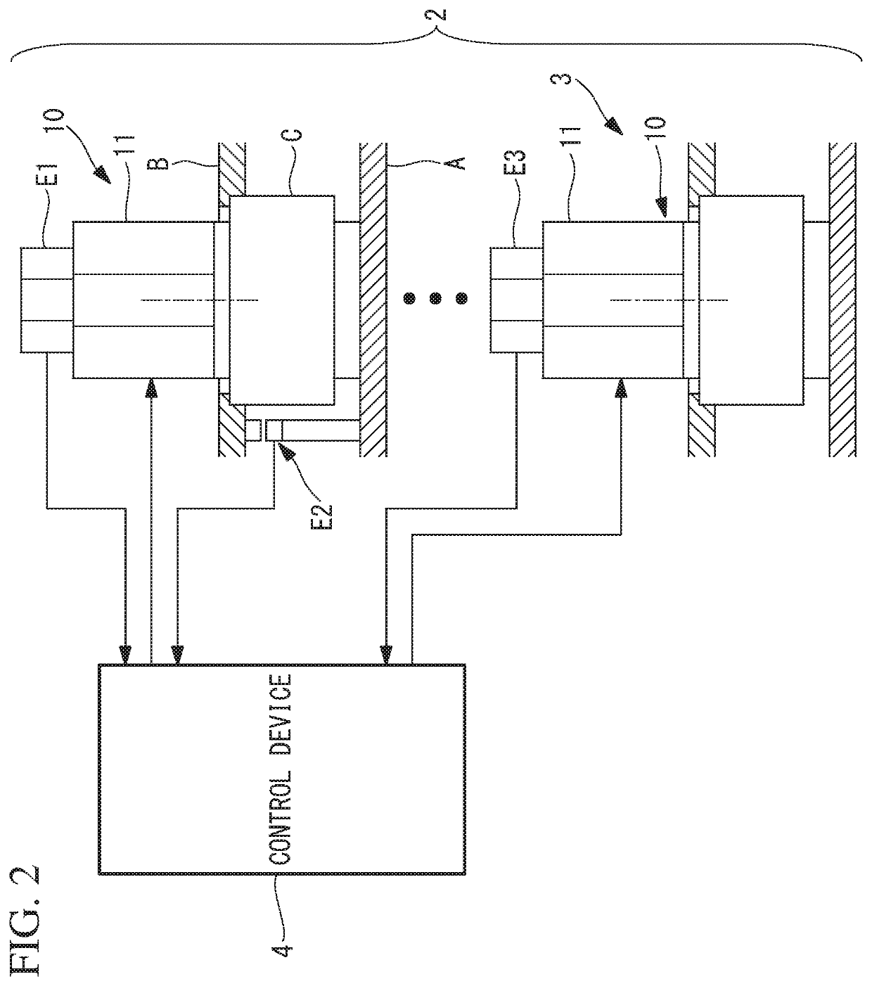
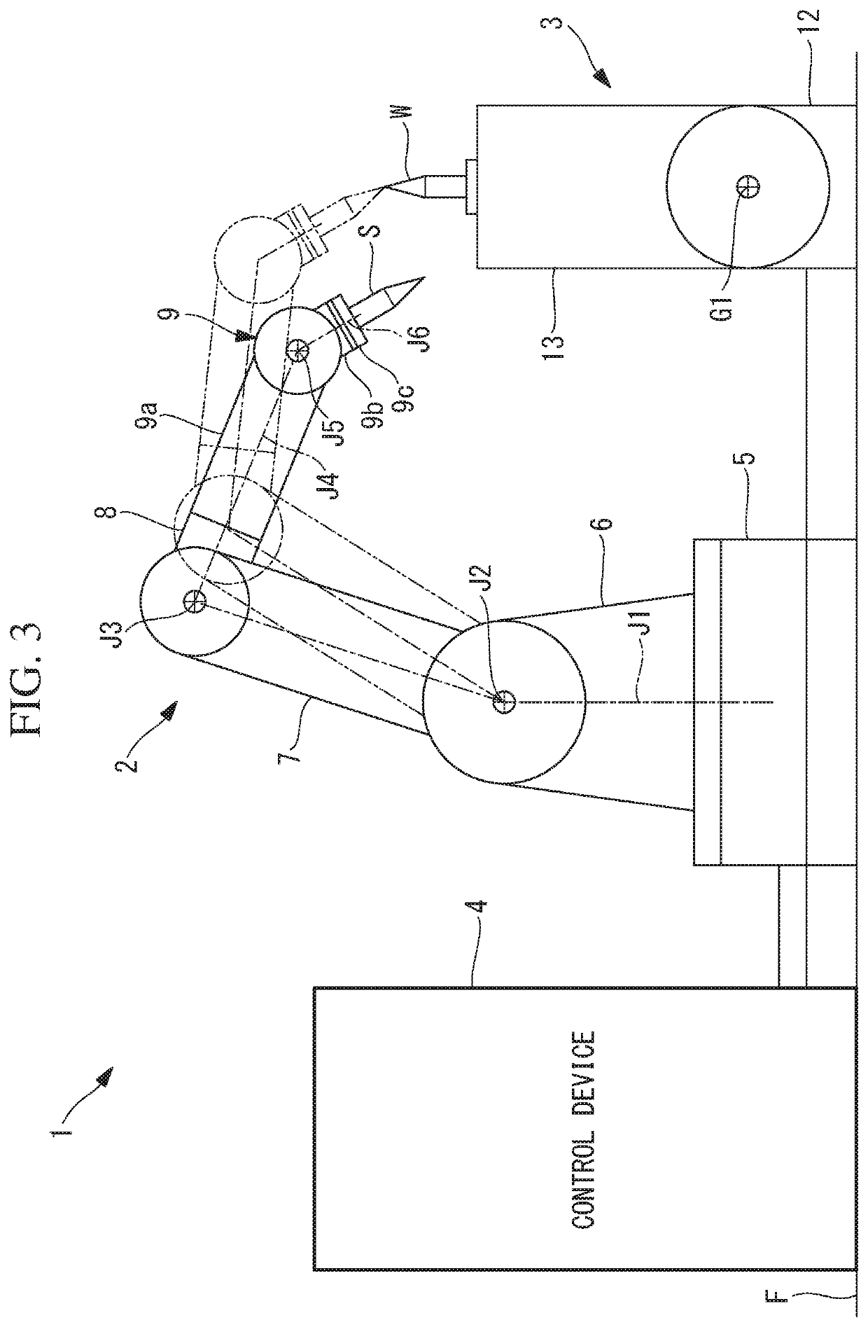
[0013]The robot system 1 according to the embodiment includes a 6-shaft articulated type robot 2 including six drive shafts 10, a positioner (external device) 3 capable of changing the position and the posture of a mounted workpiece W, and a control device 4 configured to control the robot 2 and the positioner 3, as illustrated in FIG. 1, for example.

[0014]The robot 2 includes a base 5 that is placed on a floor surface F and a pivoting body 6 supported by the base 5 so as to be able to rotate about a vertical first axial line J1. Also, the robot 2 includes a first arm 7 supported by the pivoting body 6 so as to be able to rotate about a horizontal second axial line J2 and a second arm 8 supported by the first arm 7 so as to be rotate about a third axial line J3 that is parallel to the second axial line J2. Further, the robot 2 includes a three-shaft wrist unit


PUM


Abstract

A robot system includes: a robot including drive shafts; and a control device configured to control the robot, in which each of the drive shafts includes a drive unit configured to cause a second member to operate with respect to a first member, the drive unit includes a motor, a deceleration mechanism configured to decelerate rotation of the motor and supply the rotation to the first member and the second member, and an input-side detector configured to detect a rotation angle position of the motor, at least one drive unit includes an output-side detector configured to detect an operation position of the second member with respect to the first member, and the control device controls the motor such that each of the drive shafts with high responsiveness is caused to operate with priority, on the basis of the detected rotation angle position of the motor and the detected operation position.

Description


Claims


Application Information

Patent Timeline
Owner FANUC LTD
Why Eureka
Try Eureka