Thermal storage type vacuum tube

A vacuum tube, heat storage technology, applied in heat storage equipment, energy storage, heating devices, etc., can solve problems such as water temperature rise, box 5 corrosion, high temperature and high pressure, etc., to prolong service life and increase heat exchange. area, and the effect of improving heat exchange efficiency

Inactive Publication Date: 2010-02-03
北京桑达太阳能技术有限公司
View PDF0 Cites 12 Cited by
  • Summary
  • Abstract
  • Description
  • Claims
  • Application Information

AI Technical Summary

Benefits of technology

The inventor describes an improved way for storing energy by utilizing a special type of container called a tank made up of two parts - both inside and outside of another part. Water flows into this space while work substances (such as ice) move between them. By connecting these components together at regular intervals, they create a stable system where all materials have equal temperatures when needed without causing damage during use. Overall, this technology improves the performance and lifespan of heat accumulation devices like evacuated piping systems.

Problems solved by technology

This patented technical solution described by the current design uses heat collection vacuums or pipings to transfer collected lightweight warm liquid onto another medium like groundwater without causing damage during use overtime due to continuous coolant circulations caused by elevated temperatures and pressures within them. Titanium alloys are commonly chosen based upon their cost effectiveness compared to stainable materials such as chrome plats.

Method used


Image

  • Thermal storage type vacuum tube
  • Thermal storage type vacuum tube
  • Thermal storage type vacuum tube

Examples


Embodiment Construction

[0015] The present invention will be described in detail below in conjunction with the accompanying drawings and embodiments.

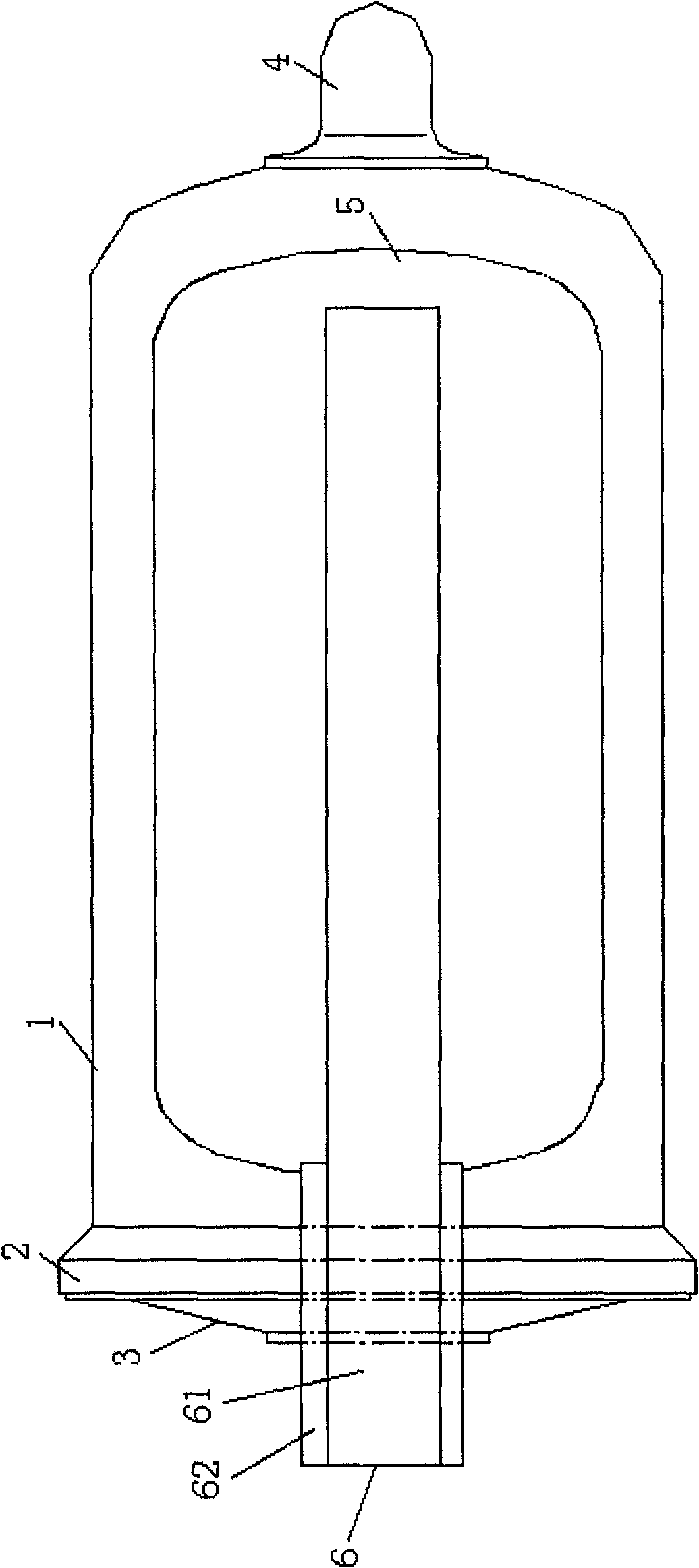
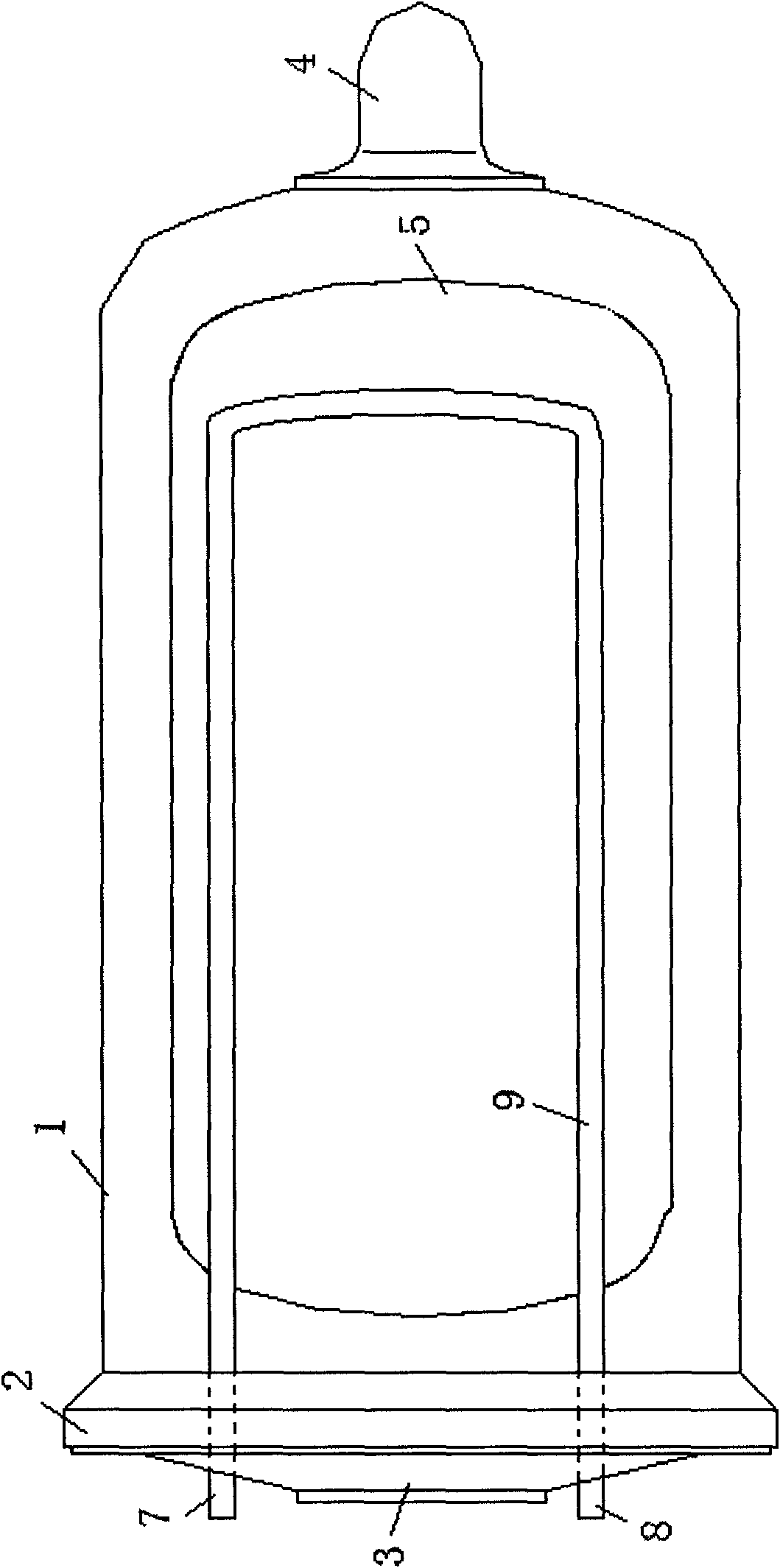
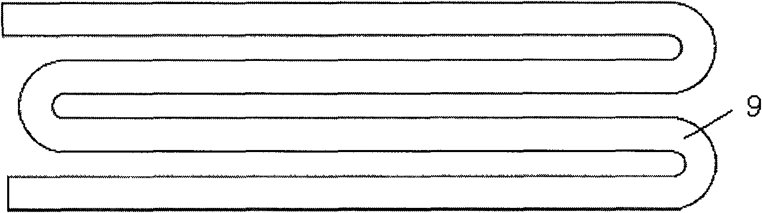
[0016] Such as figure 2 As shown, the present invention includes the same glass shell 1, glass flange 2, metal end cap 3, exhaust nozzle protective cap 4 and metal material box body 5 as the prior art, and is characterized in that the metal end cap 3 is respectively provided with a The water inlet 7 is connected to a water outlet 8 , and the water inlet 7 and the water outlet 8 are connected through a heat exchange tube 9 arranged in the box body 5 . At the same time, the working medium in the box body 5 is a solid-liquid phase change material with a phase change temperature in the range of 60°C to 80°C.

[0017] When the present invention is in use, solar energy is absorbed through the solar selective coating on the outer surface of the box body 5, and the phase change material in the box body 5 is heated. Due to the characteristics of the phase chan


PUM


Abstract

The invention relates to a thermal storage type vacuum tube which comprises a tubular glass outer shell, an open end of the glass outer shell is connected with a glass flange, the glass flange is connected with a metal end cover through the hot-pressing sealing technology, a protective cap of an exhaust nozzle is arranged at the other end of the glass outer shell, an exhaust nozzle which is integrally molded with the glass outer shell is arranged in the protective cap of the exhaust nozzle, a metal material box body is arranged in the glass outer shell, a solar energy selective coating is arranged on the outer surface of the box body, space between the glass outer shell and the box body is pumped into vacuum state through the exhaust nozzle, a water inlet and a water outlet are respectively formed on the metal end cover, the water inlet and the water outlet are communicated through a heat exchange tube arranged in the box body, and a working medium in the box body adopts solid-liquid phase change materials with phase change temperature of 60DEG C-80DEG C. The working medium in the box body adopts the solid-liquid phase change materials, when the solid-liquid phase change materialsachieve the phase change point, the materials are converted to liquid state from solid state, and a large amount of heat is absorbed, and the temperature of the phase change materials can be basicallymaintained constant. The thermal storage type vacuum tube can be widely applied in a variety of solar water heaters.

Description


Claims


Application Information

Patent Timeline
Owner 北京桑达太阳能技术有限公司
Why Eureka
Try Eureka