Blade lock

A blade lock and blade technology, applied in the field of blade locks, can solve the problems of poor anti-theft performance, decreased security, unstable performance, etc., and achieve the effects of improving safety and anti-theft performance, easy to manufacture and use, and strong anti-theft performance

Inactive Publication Date: 2010-02-24
吴其良
View PDF0 Cites 2 Cited by
  • Summary
  • Abstract
  • Description
  • Claims
  • Application Information

AI Technical Summary

Benefits of technology

This patented innovation allows for improved security features on locks used in vehicles or other applications where they are subjected to frequent changes during operation (such as when someone tries to enter). By incorporating certain technical means like slotted holes into the design of these locks, errors caused by their movements may become less stable compared to traditional designs while still being effective even if some parts have been worn out overtime. Additionally, the new design uses different types of material instead of regular steel plates making them easier to process and reduce costs. Overall, this improvements improve the overall effectiveness and ease of usage of such locks.

Problems solved by technology

The technical problem addressed by this patented solution is that existing antithetical cabinlocks have complicated mechanisms for fixing them onto the door panels, making it difficult if they require replacement due to changing users' preferences or changes made over time. Additionally, current designs may result in poor resistance against intruders but also increase their risk of being copied without permission from authorized individuals.

Method used


Image

  • Blade lock
  • Blade lock
  • Blade lock

Examples


Embodiment Construction

[0022] The present invention will be further described in detail below with reference to the embodiments of the accompanying drawings.

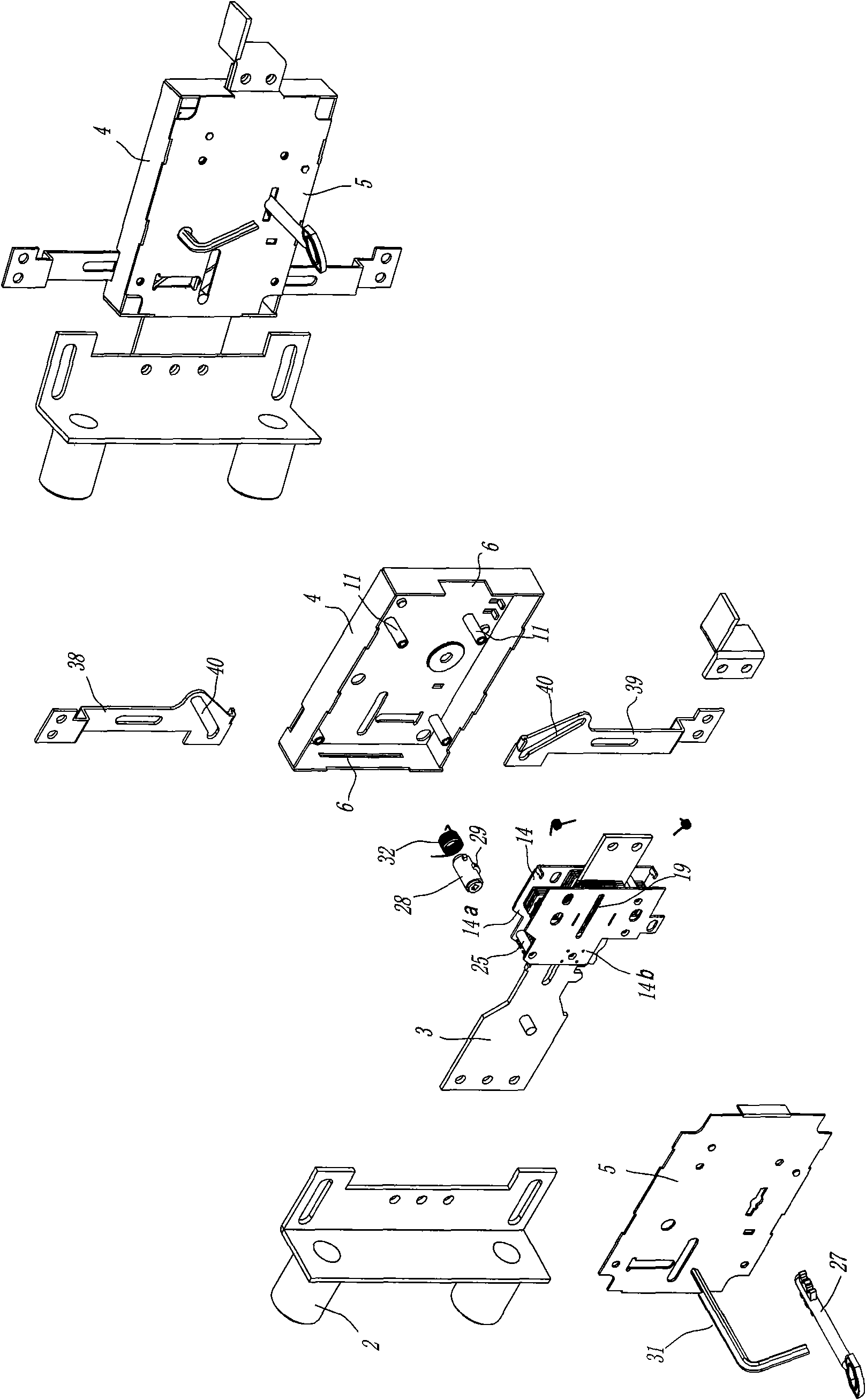
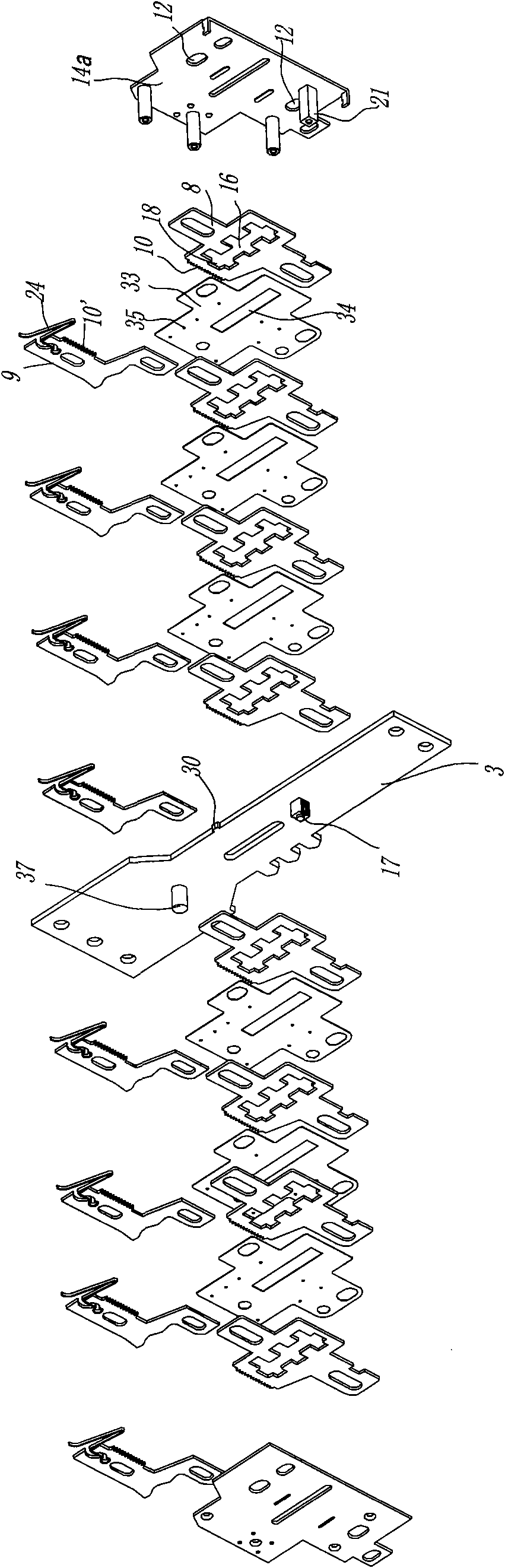
[0023] As shown in the figure, a kind of blade lock includes a lock shell 1, a lock tongue 2 and a lock tongue drag plate 3 connected with the lock tongue, wherein the lock shell 1 is divided into a lock shell base 4 and a lock cover 5, which are connected by screws. After the lock case 1 is installed, the left and right sides of the lock case 1 (as shown in the figure) are provided with openings 6, so that the lock tongue extension plate 3 is limited in the opening of the lock case 1 and can be moved laterally. There are blade groups 7 stacked on the sides. In this embodiment, a blade group 7 is stacked on each of the two sides of the lock tongue carriage 3. Each blade group 7 includes several blades, and the blades are divided into variable blades 8 and variable blades. There are two kinds of tooth pieces 9. The variable blade 8 is provided wi


PUM


Abstract

The invention discloses a blade lock, which is characterized in that: a blade is divided into a variable blade and a variable dentate sclerite; the side edge of the variable blade is provided with a rack for forming a key differential; the variable blade is limited in a lock shell and capable of moving up and down; the variable blade is provided with a transversely arranged hollow dental groove matched with a lock cylinder; correspondingly, the lateral surface of an extension plate of a lock bolt is provided with the variable dentate sclerite which can move left and right along with the extension plate of the lock bolt; the side edge of the variable dentate sclerite is also provided with a rack which is matched and engaged with the variable blade; a curvilinear surface matched with a key is arranged below the variable dentate sclerite; the inside of the lock shell is provided with a bias element for making the variable dentate sclerite have a bias trend along a predetermined path, anda drive mechanism for driving the variable dentate sclerite and the variable blade separate from or combine with each other. The blade lock has the function of changing keys repeatedly at any time without changing a lock so as to improve the security anti-theft function; and the blade lock has more convenient use, better anti-theft performance, reasonable and simple structure and easy manufactureand use.

Description


Claims


Application Information

Patent Timeline
Owner 吴其良
Why Eureka
Try Eureka