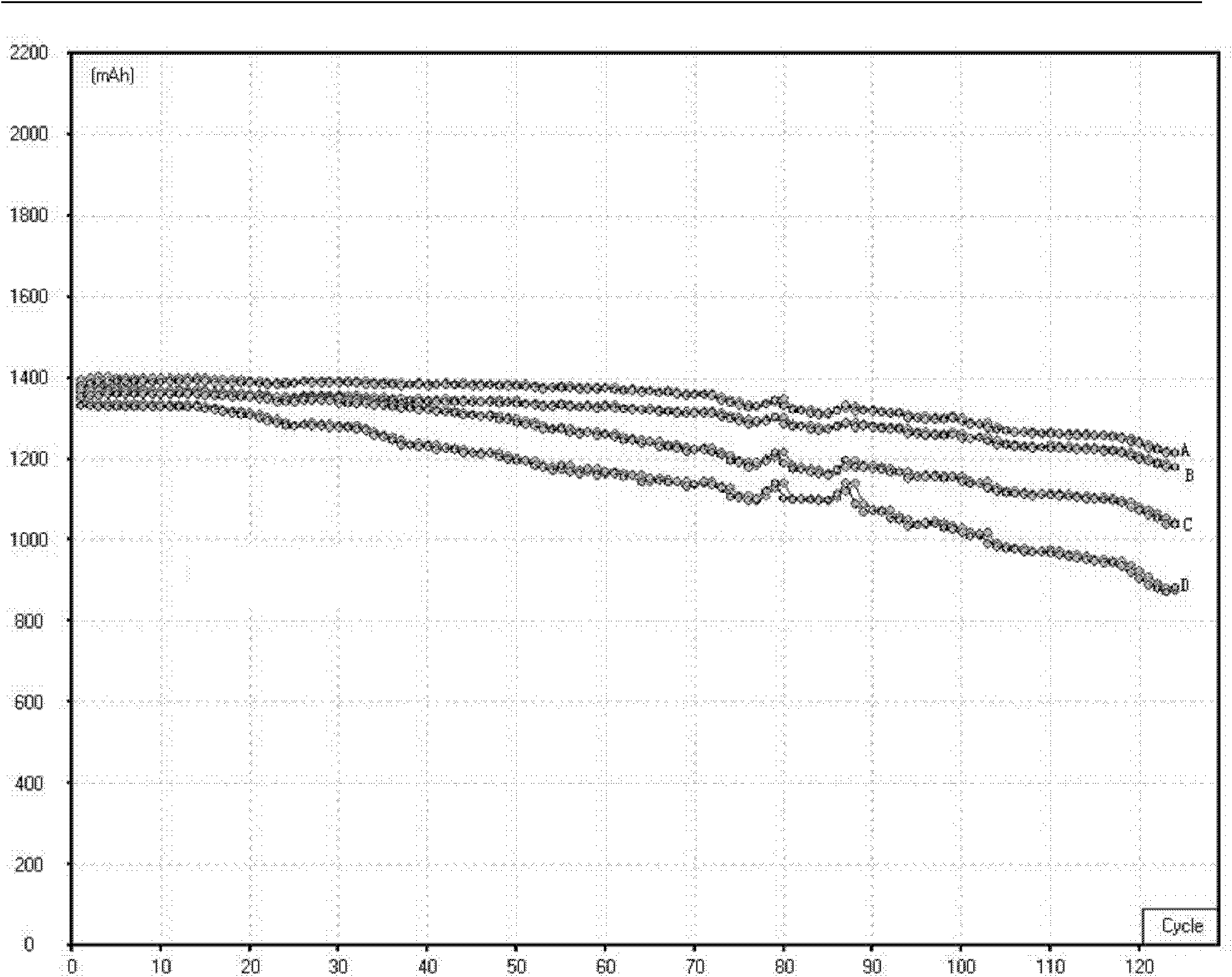
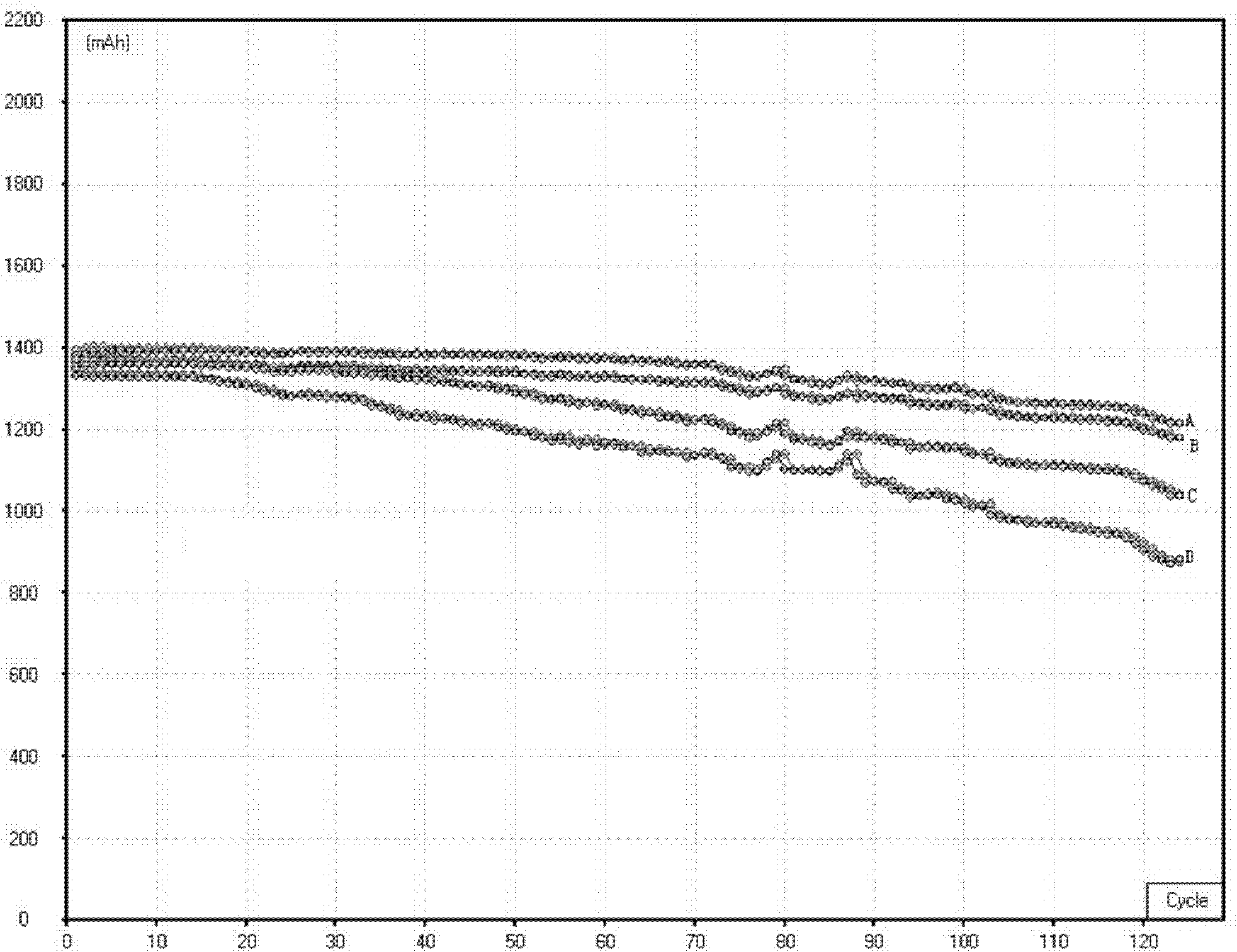
Porous metal material and preparation method thereof
A porous metal and metal technology, applied in alkaline storage battery electrodes, electrolysis process, electroforming, etc., can solve problems such as impact and fracture that cannot withstand large currents, affect battery life and use safety, and achieve improved fracture and The effect of excessive internal resistance, improving corrosion resistance, and enhancing work safety
- Summary
- Abstract
- Description
- Claims
- Application Information
AI Technical Summary
Problems solved by technology
Method used
Image
Examples
Embodiment 1
[0012] Example 1 The polyurethane sponge material with a thickness of 2.0mm is used as the substrate, and the preparation is carried out according to the following process: conductive treatment of the substrate - the first electrochemical deposition - the first heat treatment - rolling - surface treatment - the second The second electrochemical deposition - the second heat treatment.
[0013] Among them, the conductive treatment adopts the physical vapor deposition method, using high-purity electrolytic nickel target as the sputtering substrate, in a vacuum of 1.8*10 -2 Pa, sputtering power 3.5Kw, target distance 40mm under the process conditions, adopt physical vapor deposition to deposit a nickel layer on the polyurethane sponge substrate, the nickel deposition amount is 0.3g / m 2 .
[0014] The first electrochemical deposition adopts ordinary Watts nickel electrodeposition process and equipment to deposit a nickel layer on the above-mentioned conductive substrate, and cont
Embodiment 2
[0021] Example 2 Porous nickel material is prepared in substantially the same manner as in Example 1, and its different process conditions are as follows: 1. The thickness of the original polyurethane sponge base material is 10mm; 2. The amount of electrochemically deposited nickel for the first time is 1000g / m 2 ; 3. The reduction temperature of the first heat treatment is 1100°C; 4. Rolling to a thickness of 9.5mm, soaking time in dilute nitric acid solution is 30min; 5. In the second electrochemical deposition step, the double anode area is different , the area ratio is 1:5, and the amount of nickel deposited on the side corresponding to the small anode is controlled to be 50g / m 2 ; 6. The second heat treatment is vacuum heat treatment, the temperature is 700°C, and the material is kept warm for 3 hours per square meter.
[0022] The porous nickel material prepared by the above method is measured, along the thickness direction of the material, from top to bottom (note: t
Embodiment 3
[0023] Example 3 Porous nickel material is prepared in substantially the same manner as in Example 1, and the different process conditions are as follows: 1. The thickness of the original polyurethane sponge base material is 1.6mm; 2. The amount of electrochemically deposited nickel for the first time is 500g / m 2 ; 3. The reduction temperature of the first heat treatment is 900°C; 4. Rolling to a thickness of 1.5mm, soaking time in dilute hydrochloric acid solution is 10min; 5. In the second electrochemical deposition step, the double anode area is different , the area ratio is 1:3, and the amount of nickel deposited on the side corresponding to the small anode is controlled to be 100g / m 2 ; 6. The second heat treatment is vacuum heat treatment, the temperature is 500°C, and the material is kept warm for 0.5 hours per square meter.
[0024] The porous nickel material prepared by the above method is measured, along the thickness direction of the material, from top to bottom
PUM
| Property | Measurement | Unit |
|---|---|---|
| Thickness | aaaaa | aaaaa |
| Thickness | aaaaa | aaaaa |
| Thickness | aaaaa | aaaaa |
Abstract
Description
Claims
Application Information
 - R&D Engineer
- R&D Manager
- IP Professional
- Industry Leading Data Capabilities
- Powerful AI technology
- Patent DNA Extraction
Browse by: Latest US Patents, China's latest patents, Technical Efficacy Thesaurus, Application Domain, Technology Topic.
© 2024 PatSnap. All rights reserved.Legal|Privacy policy|Modern Slavery Act Transparency Statement|Sitemap


