Fixture for forming U-shaped clip of steel plate spring

A leaf spring, U-shaped technology is applied in the field of tooling for forming U-shaped clips of automobile leaf springs, which can solve the problems of unstable positioning, cumbersome positioning adjustment, large accumulation and loss of waste products, etc., to achieve high forming size accuracy and reduce waste products loss. , the effect of reducing the generation of waste

Inactive Publication Date: 2012-01-25
诸城市恒信基汽车部件有限公司
View PDF0 Cites 6 Cited by
  • Summary
  • Abstract
  • Description
  • Claims
  • Application Information

AI Technical Summary

Problems solved by technology

[0002] There are many U-shaped clips used for installing leaf springs in automobiles. The current tooling is cumbersome to adjust the position

Method used


Image

  • Fixture for forming U-shaped clip of steel plate spring
  • Fixture for forming U-shaped clip of steel plate spring

Examples


Embodiment Construction

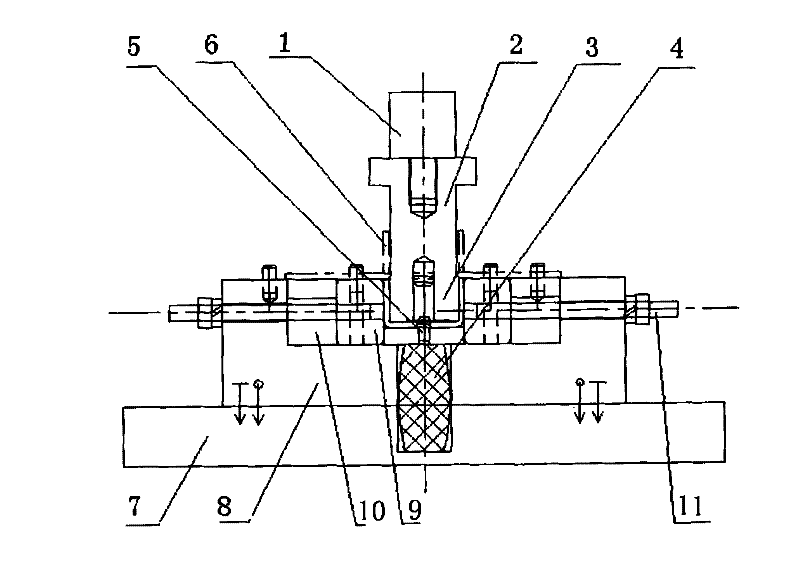
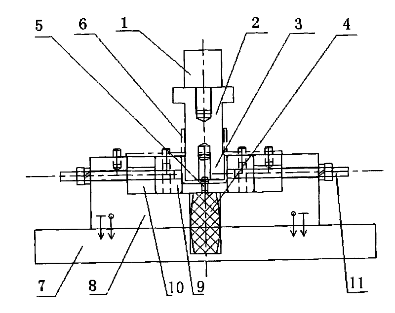
[0009] Such as figure 1 As shown, the present invention is respectively connected with the mold handle 1 and the upper module 3 at the upper end and the lower end of the upper mold fixing block 2, and a lower mold fixing block 8 is provided on the upper end surface of the lower template 7, and the upper end both sides of the lower mold fixing block 8 are respectively A lower module 9 and a gap adjustment backing plate 10 are provided, and the lower module 9 and the gap adjustment backing plate 10 are laterally fixed on both sides of the upper end of the lower mold fixing block 8 by locking bolts 11, and the gap between the two lower modules 9 is the same as that of the upper Corresponding to the module 3, an elastic stripping body 4 with a positioning pin 5 is arranged in the middle of the lower mold fixing block 8, and the positioning pin 5 corresponds to the center hole of the upper module 3. Through the above settings, when the present invention is working, the upper module 3


PUM


Abstract

The invention discloses a fixture for forming a U-shaped clip of a steel plate spring. The fixture is characterized in that: a die shank and an upper module are connected with the upper end and the lower end of an upper die fixing block respectively; a lower die fixing block is arranged on the upper end face of a lower template; two lower modules and a gap regulation base plate are arranged on two sides of the upper end of the lower die fixing block respectively; a gap between the two lower modules corresponds to the upper module; and an elastic material return body with a positioning pin is arranged in the middle of the lower die fixing block. Due to the arrangement, the die shank and the lower template are connected with an upper stamping head and a working table of a pressure machine respectively, so the fixture can form U-shaped clips of steel plate springs of different specifications by bending.

Description


Claims


Application Information

Patent Timeline
Owner 诸城市恒信基汽车部件有限公司
Why Eureka
Try Eureka