Adjusting method of resonant cavity

An adjustment method and resonant cavity technology, applied in the field of lasers, can solve the problems of inability to achieve laser maintenance and debugging, increased difficulty in adjusting the resonant cavity, larger spot size, etc., and achieve the effects of simple structure, low cost, and easy implementation.

Inactive Publication Date: 2012-07-04
BEIJING GK LASER TECH
View PDF5 Cites 9 Cited by
  • Summary
  • Abstract
  • Description
  • Claims
  • Application Information

AI Technical Summary

Benefits of technology

This technology allows an oscillating circuit (resonance) chamber to have two reflective surfaces - either a reflection surface or another type of reflector called a signal lens. These reflections help it focus signals on different parts inside its space faster than if they were all at once. By adding this design to existing circuits without changing their components, we aimed towards improving efficiency and accuracy over time while also simplifying construction costs.

Problems solved by technology

The technical problem addressed in this patented technology relating to tunable diode lasers (TDL) has been that current methods are time-consuming or require complicated equipment like Helium-Neons Lasers, while also requiring specific materials at high cost due to their use.

Method used


Image

  • Adjusting method of resonant cavity
  • Adjusting method of resonant cavity
  • Adjusting method of resonant cavity

Examples


Embodiment Construction

[0016] The adjustment method of the resonant cavity of the present invention comprises the following four steps:

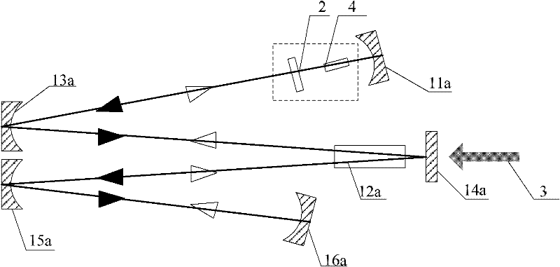
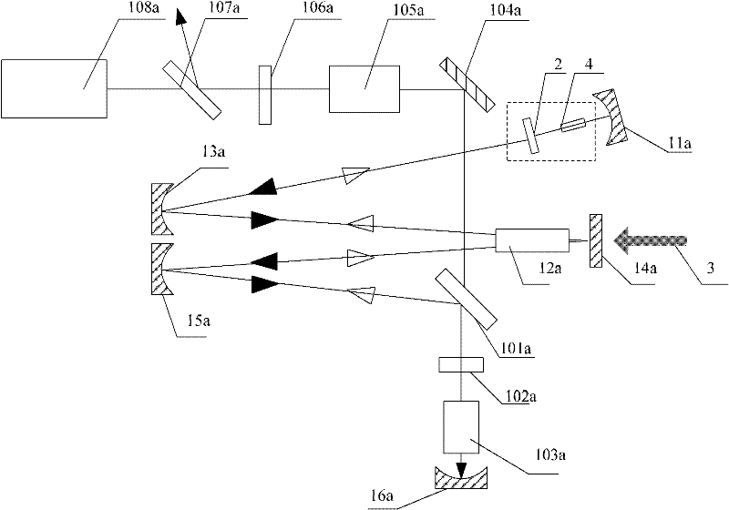
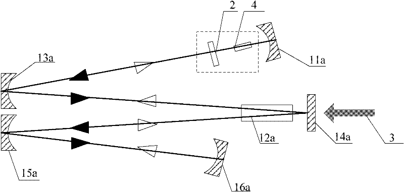
[0017] Step 1: Set the first-end resonant mirror and the second-end resonant mirror at both ends of the optical path of the resonator respectively, and set at least two reflective cavity mirrors between the first-end resonant mirror and the second-end resonant mirror and arranged sequentially along the optical path, the gain medium is arranged between two adjacent reflective cavity mirrors;

[0018] Step 2: Put the signal light gain medium between the first resonant cavity mirror in the resonant cavity optical path and the reflective cavity mirror closest to the first end resonant cavity mirror, and put the signal light output mirror into the signal in the resonant cavity optical path The side of the optical gain medium away from the first end resonant cavity mirror, and the signal light output mirror, the signal light gain medium and the first end resonant cavity mi


PUM


Abstract

The invention relates to an adjusting method of a resonant cavity. The method comprises the steps that a signal light output mirror and a signal light gain medium are additionally arranged at one end of the resonant cavity, so that the signal light output mirror, the signal light gain medium and an end resonant cavity mirror of the resonant cavity form a reference light resonant cavity, the reference light resonant cavity outputs a reference light under the irradiation of a pump light, and the reference light can be used for quickly and accurately adjusting the positions of other reflection cavity mirrors in the resonant cavity. Compared with the cavity mirror adjusting method employing He-Ne light in the prior art, the adjusting method is simpler and more accurate, avoids the limits on use occasions and is particularly applicable to field equipment debugging and maintenance and the like under insufficient conditions. Besides, an adjusting device only comprises the signal light output mirror, so that the structure is simple, the implementation is easy and the cost is low.

Description


Claims


Application Information

Patent Timeline
Owner BEIJING GK LASER TECH
Why Eureka
Try Eureka