High-strength engine cover plate

An engine cover and high-strength technology, which is applied in the field of automobile flywheels, can solve problems such as parts damage, and achieve the effects of reliable connection, high connection quality and high mechanical strength

Inactive Publication Date: 2013-01-30
刘枫
View PDF0 Cites 1 Cited by
  • Summary
  • Abstract
  • Description
  • Claims
  • Application Information

AI Technical Summary

Benefits of technology

This new type of engine covers have better connections with other parts than traditional ones due to their stronger structure. These improvements make them last longer without losing its effectiveness or causing problems during use.

Problems solved by technology

This patented technical problem addressed by this patents relates to ensuring that an automobile's engine covers have sufficient protection against outside forces such as impact from collisions or other factors like vibrations caused during driving conditions for safety purposes.

Method used


Image

  • High-strength engine cover plate

Examples


Embodiment Construction

[0013] The preferred embodiments of the present invention will be described in detail below in conjunction with the accompanying drawings, so that the advantages and features of the present invention can be more easily understood by those skilled in the art, so as to define the protection scope of the present invention more clearly.

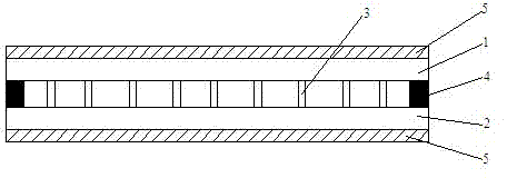
[0014] see figure 1 , the embodiment of the present invention includes:

[0015] A high-strength engine cover plate includes: an upper cover plate 1 , a connecting piece 3 and a lower cover plate 2 , and the upper cover plate 1 and the lower cover plate 2 are fixedly arranged through a plurality of connecting pieces 3 .

[0016] The plurality of connecting pieces 3 are arranged vertically between the upper cover 1 and the lower cover 2 to ensure reliable connection between the upper cover 1 and the lower cover 2 .

[0017] In the present invention, the plurality of connecting pieces 3 are equally spaced and evenly distributed, which ensures the uni


PUM

PropertyMeasurementUnit
Monofilament diameteraaaaaaaaaa

Abstract

The invention discloses a high-strength engine cover plate which comprises an upper cover plate, connection plates and a lower cover plate. The upper cover plate and the lower cover plate are fixedly arranged through a plurality of the connection plates, the connection position of two ends of the upper cover plate and the lower cover plate is fixedly provided with a steel plate, and the upper surface of the upper cover plate and the lower surface of the lower cover plate are provided with glass fibers. According to the high-strength engine cover plate, by means of the way, the connection between the upper cover plate and the lower cover plate is reliable, stable and high in quality, and mechanical strength is high so that good compression strength of the cover plate is guaranteed.

Description


Claims


Application Information

Patent Timeline
Owner 刘枫
Why Eureka
Try Eureka