Decorating body and decoration display device employing decorating body
A technology of decorative body and light guide body, which is applied to patterns and light guides characterized by decorative arts and light projection effects, can solve the problems of difficult light transmission, inability to uniformly emit three-dimensional patterns, and leakage, and achieve the effect of thinning
- Summary
- Abstract
- Description
- Claims
- Application Information
AI Technical Summary
Problems solved by technology
Method used
Image

Examples
no. 1 approach ]
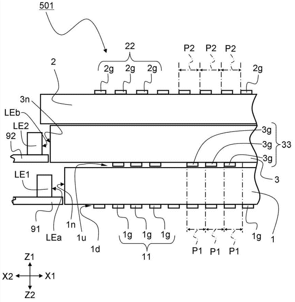
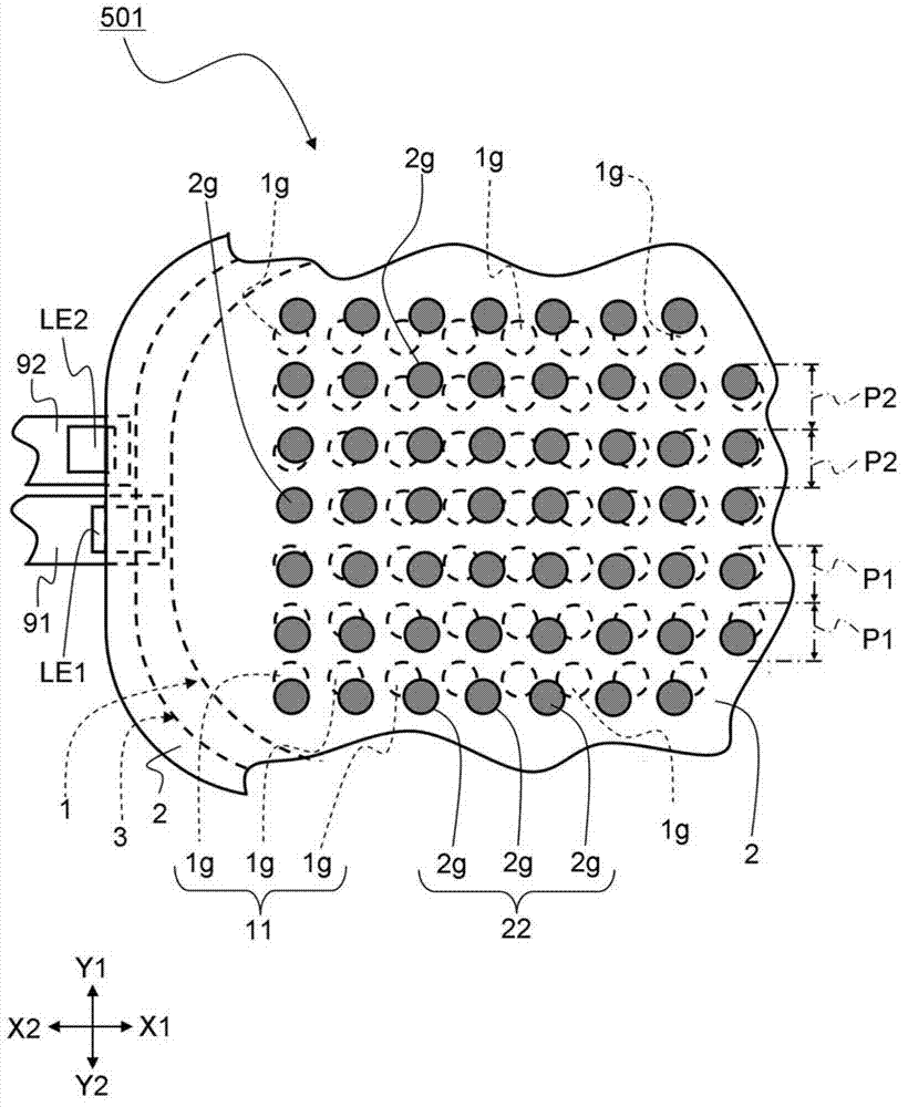
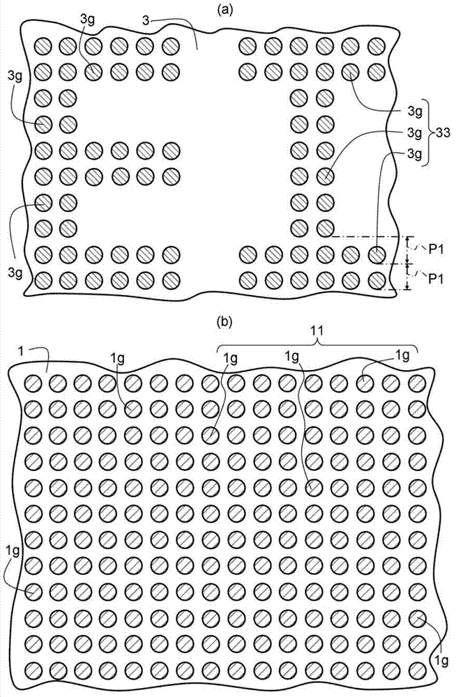
[0069] figure 1 It is a side view illustrating the structure of the decorative body 501 according to the first embodiment of the present invention. In addition, for convenience of description, a part of the decorative body 501 is shown. figure 2 It is a structural diagram illustrating the decorative body 501 according to the first embodiment of the present invention, from figure 1 Top view from Z1 side view shown. Also, for the sake of illustration, in figure 2 The third pattern is omitted in . image 3 It is a structural diagram explaining the ornamental body of 1st Embodiment of this invention, image 3 (a) is a plan view showing the third pattern 33 , image 3 (b) is a top view showing the first pattern 11 . Figure 4 It is a structural diagram explaining the ornamental body of 1st Embodiment of this invention, and is the image 3 The top view of the first pattern 11 and the third pattern 33 after overlapping is shown. Also, for the sake of illustration, in image
no. 2 approach ]
[0095] Figure 5 It is a side structural view explaining the decoration body 502 of 2nd Embodiment of this invention. Image 6 It is a configuration diagram illustrating a decorative body 502 according to a second embodiment of the present invention, taken from Figure 5 Top view from Z1 side view shown. Also, for the sake of illustration, in Image 6 The third pattern 233 is omitted. Figure 7 It is a configuration diagram illustrating a decorative body according to a second embodiment of the present invention, Figure 7 (a) is a plan view showing the third pattern 233, Figure 7 (b) is a plan view showing the second pattern 222 . Figure 8 It is a configuration diagram illustrating a decorative body according to a second embodiment of the present invention, and is a Figure 7 The top view of the overlapping of the second pattern 222 and the third pattern 233 is shown. In addition, compared with the first embodiment, the decorative body 502 of the second embodiment has di
no. 3 approach ]
[0111] Figure 9 It is a side structural view explaining the decorative body 503 of 3rd Embodiment of this invention. Figure 10 It is a configuration diagram illustrating a decorative body 503 according to a third embodiment of the present invention, from Figure 9 Top view from Z1 side view shown. The decorative body 503 of the third embodiment differs from the first embodiment mainly in that the second light guide body 3 is not provided. In addition, about the same structure as 1st Embodiment, the same code|symbol is attached|subjected, and detailed description is abbreviate|omitted.
[0112] The decorative body 503 of the third embodiment of the present invention is as Figure 9As shown, there are provided: a first light guide 301 for guiding light from the light source LE1; In addition, if Figure 9 and Figure 10 As shown, on the surface (lower surface) of the main surface of the first light guide body 301, a first pattern 311 having a plurality of first pixels 31g ar
PUM
 Abstract
Description
Claims
Application Information
 - R&D Engineer
- R&D Manager
- IP Professional
- Industry Leading Data Capabilities
- Powerful AI technology
- Patent DNA Extraction
Browse by: Latest US Patents, China's latest patents, Technical Efficacy Thesaurus, Application Domain, Technology Topic.
© 2024 PatSnap. All rights reserved.Legal|Privacy policy|Modern Slavery Act Transparency Statement|Sitemap