Convenient lag screw mold base
A technology of mold base and tension, which is applied in the field of casting molds, can solve the problems of complex picking process and low production efficiency of PDLLA tension screws, and achieve the effects of shortening mold opening time, improving production efficiency and accelerating cooling speed
- Summary
- Abstract
- Description
- Claims
- Application Information
AI Technical Summary
Problems solved by technology
Method used
Image

Examples
Example Embodiment
[0024] Example 1:
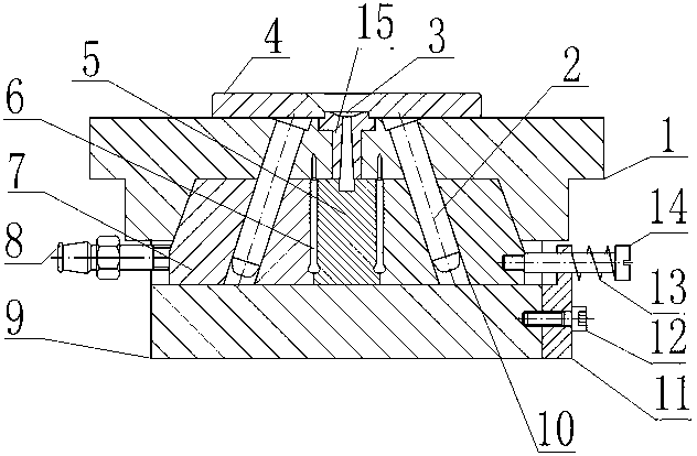
[0025] Such as figure 1 , A convenient lag screw mold base, comprising a lower mold seat pad 9, a lower mold seat fixedly connected to the upper surface of the lower mold seat pad 9, an upper mold seat 1, an upper mold seat above the lower mold seat 1 The drainage hole 3 is set in the center. The lower mold base includes a circular inner mold 5 and an outer mold 7 composed of multiple arc segments. The inner mold 5 is located in the center of the outer mold 7, and there is between the inner mold 5 and the outer mold 7. A plurality of PDLLA lag screw cavities 6, the upper mold base 1 has an inclined guide post 2 integrated therewith, and the outer mold 7 is also provided with a guide post hole 10, and also includes a brake outer mold 7 An outer mold brake mechanism that moves in the horizontal direction, and the outer mold brake mechanism is fixedly connected to the lower mold seat pad 9.
[0026] When the upper mold base moves downward under the drive of the tran
Example Embodiment
[0027] Example 2:
[0028] This embodiment is further limited on the basis of embodiment 1, such as figure 1 , A convenient lag screw mold base, including an oblique guide post 2 and a guide post hole 10, the inner surface of the guide post hole 10 is also provided with a guide sleeve, the outer diameter of the guide sleeve is larger than the inner diameter of the guide post hole 10 0.1mm, and the shaft hole mating surface of the guide sleeve and the guide post hole 10 is also provided with a flat key, the material of the guide sleeve is copper, and the material of the inclined guide post 2 is carbon steel, because the guide sleeve and the guide post hole 10 are adopted The interference fit relationship makes the guide sleeve and the guide post hole fit tightly. The diameter difference of 0.1 mm makes the guide sleeve fit into the guide post hole to complete the installation only by tapping. The guide sleeve and the shaft hole of the guide post hole are set on the mating surface Th
Example Embodiment
[0029] Example 3:
[0030] This embodiment is further limited on the basis of embodiment 1, such as figure 1 , A convenient lag screw mold base, including a water pipe interface 8, the water pipe interface 8 adopts a ferrule type taper thread straight pipe joint, and the water pipe interface 8 is connected to the peripheral pure water circulation system, and uses a ferrule taper thread straight pipe joint. Compared with other detachable connection forms, the volume is small and the weight is light, and this connection form makes the connection of the water pipe interface and the pure water circulation system convenient.
PUM
| Property | Measurement | Unit |
|---|---|---|
| The inside diameter of | aaaaa | aaaaa |
Abstract
Description
Claims
Application Information
 - R&D Engineer
- R&D Manager
- IP Professional
- Industry Leading Data Capabilities
- Powerful AI technology
- Patent DNA Extraction
Browse by: Latest US Patents, China's latest patents, Technical Efficacy Thesaurus, Application Domain, Technology Topic.
© 2024 PatSnap. All rights reserved.Legal|Privacy policy|Modern Slavery Act Transparency Statement|Sitemap