Novel vertical motor cooling system

A vertical motor and cooling system technology, applied in cooling/ventilation devices, electrical components, electromechanical devices, etc., can solve problems such as high hot air temperature, increased motor operating costs and maintenance complexity, and reduced cooler heat transfer effect. Achieve sufficient heat exchange, improve stability, and increase cooling speed

Pending Publication Date: 2018-02-27
JIANGSU AEROSPACE POWER ELECTRIC
View PDF9 Cites 0 Cited by
  • Summary
  • Abstract
  • Description
  • Claims
  • Application Information

AI Technical Summary

Problems solved by technology

In this way, the internal and external air paths of the motor can be regarded as flowing in the same direction when they are in the cooler, which reduces the heat transfer effect of the cooler
At the same time, the temperature of the hot air blown from the bottom of the cooler is relatively high, especially when the motor is running in the high temperature season, the personnel who perform relevant

Method used


Image

  • Novel vertical motor cooling system
  • Novel vertical motor cooling system
  • Novel vertical motor cooling system

Examples


Embodiment Construction

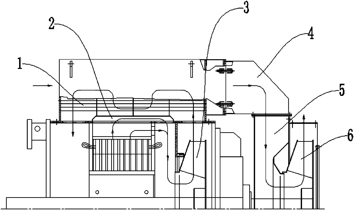
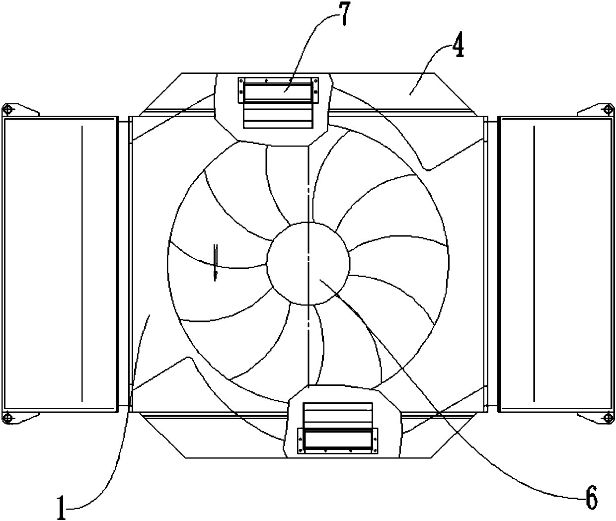
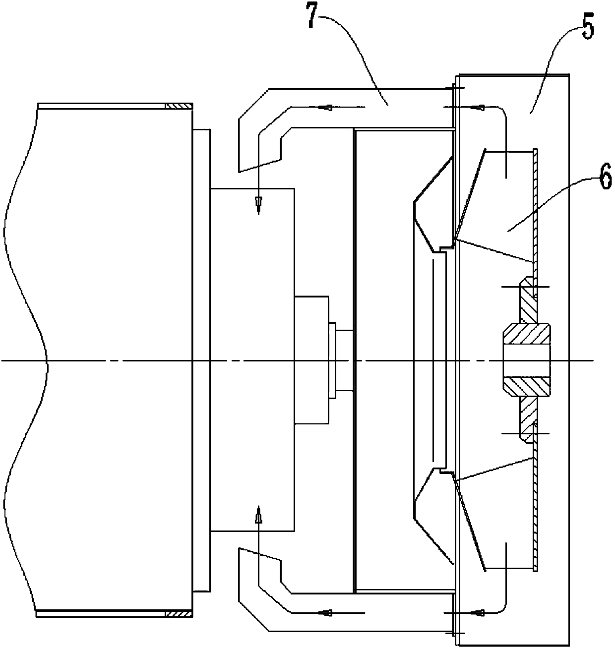
[0018] like figure 1 , figure 2 and image 3 As shown, this specific embodiment adopts the following technical solutions: it includes a cooler main body 1, an inner air path expansion compartment 2, an inner fan 3, a main air duct 4, a fan cover 5, an outer fan 6, and a counseling air duct 7. The inner motor casing at the lower end of the main body 1 is provided with an inner air passage expansion chamber 2, an inner fan 3 is arranged above the inner air passage extension chamber 2, an outer fan 6 is arranged at the upper end of the cooler main body 1, and an outer fan 6 is arranged outside the outer fan 6. The fan cover 5 is provided with a leading air cylinder 4 outside the fan cover 5, and a tutoring air cylinder 7 is arranged in the leading air cylinder 4.

[0019] Wherein, the inner air path expansion compartment 2 is fixed on the inner side of the cooler main body 1 by screws, and the outer side of the inner air path expansion compartment 2 is provided with a cooling pip


PUM


Abstract

The invention discloses a novel vertical motor cooling system, and relates to the technical field of motors. The novel vertical motor cooling system comprises a cooler main body, an inner wind path extension separating cavity, a main fan, a main wind guide cylinder, a fan cover, an outer fan and an auxiliary wind guide cylinder, wherein the inner wind path extension separating cavity is formed ina motor shell arranged at the inner side of the lower end of the cooler main body; the inner fan is arranged above the inner wind path extension separating cavity; the outer fan is arranged on the upper end of the cooler main body; the fan cover is arranged at the outer part of the outer fan; the main wind guide cylinder is arranged at the outer part of the fan cover; the auxiliary wind guide cylinder is arranged in the main wind guide cylinder. According to the novel vertical motor cooling system disclosed by the invention, heat exchange is more sufficient and more efficient, and the coolingspeed of a motor is increased; meanwhile, a top bearing can be cooled, an external apparatus is not needed, the equipment operation stability is increased, and a more friendly working environment canbe provided for a motor operation scene.

Description


Claims


Application Information

Patent Timeline
Owner JIANGSU AEROSPACE POWER ELECTRIC
Why Eureka
Try Eureka