Tunnel fireproof plate and production process thereof
A production process and technology of fireproof boards, which are applied in the formulation field of tunnel fireproof boards, can solve the problems of complex production process, low flexural strength, short fire resistance time of fireproof boards, etc., and achieve the effect of simple production process and reduced loss.
- Summary
- Abstract
- Description
- Claims
- Application Information
AI Technical Summary
Problems solved by technology
Method used
Image

Examples
Example Embodiment
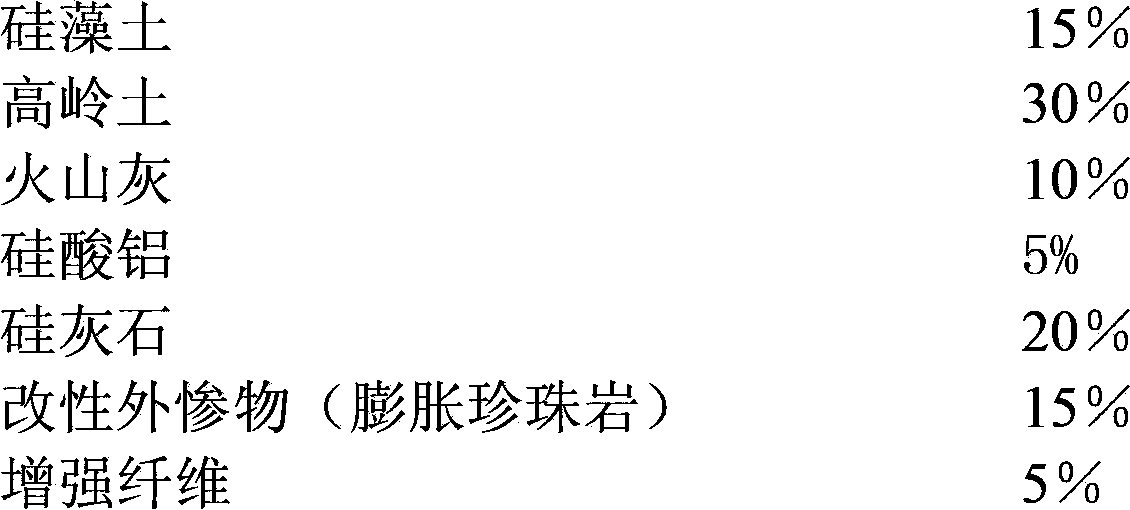
[0036] Example 1
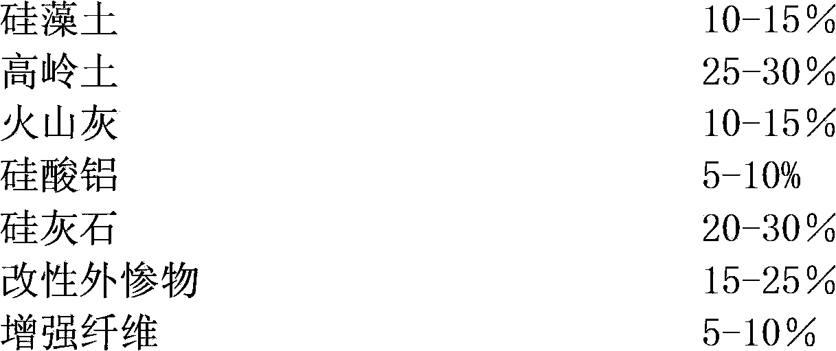
[0037] The weight percentage of solid filler is:
[0038]
[0039] The production process includes the following steps: a. The weight percentage of each component of the solid filler is: 15% diatomaceous earth, 30% kaolin, 10% pozzolan, 5% aluminum silicate, 20% wollastonite, and modified external 15% of the filler and 5% of the reinforcing fiber. The total weight percentage of the above filler is 100%. After the above solid filler is prepared, fully stir it for 10-15 minutes for standby; b. Make liquid slurry, liquid slurry and solid The weight percentage of the filler is 20:80, the liquid slurry is prepared by using magnesium chloride: magnesium oxide (molar ratio) = 1:1.5~1.0 to prepare a certain consistency of magnesium oxychloride slurry, and the solid filler is added to the liquid slurry and stirred 5-10 minutes, then add the solid filler into it and stir evenly; c. Put the above mixture into three drums for extrusion, and the extrusion pressure is 2-3kg / cm
Example Embodiment
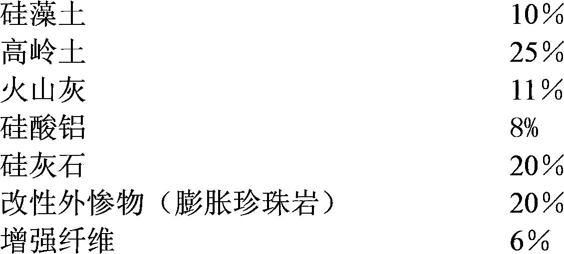
[0040] Example 2
[0041] The weight percentage of solid filler is:
[0042]
[0043] After mixing, forming, curing and cutting the formulas of the above two examples, see Table 2
[0044] Table 2 Performance Comparison of Examples
[0045] .
PUM
 Abstract
Description
Claims
Application Information
 - R&D Engineer
- R&D Manager
- IP Professional
- Industry Leading Data Capabilities
- Powerful AI technology
- Patent DNA Extraction
Browse by: Latest US Patents, China's latest patents, Technical Efficacy Thesaurus, Application Domain, Technology Topic.
© 2024 PatSnap. All rights reserved.Legal|Privacy policy|Modern Slavery Act Transparency Statement|Sitemap