Solid heat accumulating type heat exchanger for pipeless waste heat utilization

A technology of heat exchanger and heat storage type, which is applied in the direction of heat exchanger types, indirect heat exchangers, heat storage equipment, etc., and can solve the problem of complex structure, high cost, and large heat exchanger volume of heat storage and heat release systems. Problems, to achieve the effect of heat storage capacity and cost, increase capacity, uniform heat storage

Active Publication Date: 2014-07-30
山东中和热工科技有限公司
View PDF4 Cites 16 Cited by
  • Summary
  • Abstract
  • Description
  • Claims
  • Application Information

AI Technical Summary

Problems solved by technology

However, the existing problems are that the structure of the heat storage and heat release system is complex, the heat exchanger for heat stor

Method used


Image

  • Solid heat accumulating type heat exchanger for pipeless waste heat utilization
  • Solid heat accumulating type heat exchanger for pipeless waste heat utilization
  • Solid heat accumulating type heat exchanger for pipeless waste heat utilization

Examples


Embodiment Construction

[0035] The specific embodiments of the present invention will be described in detail below in conjunction with the accompanying drawings.

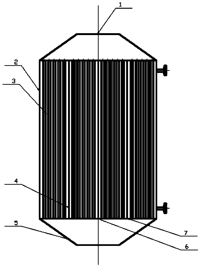
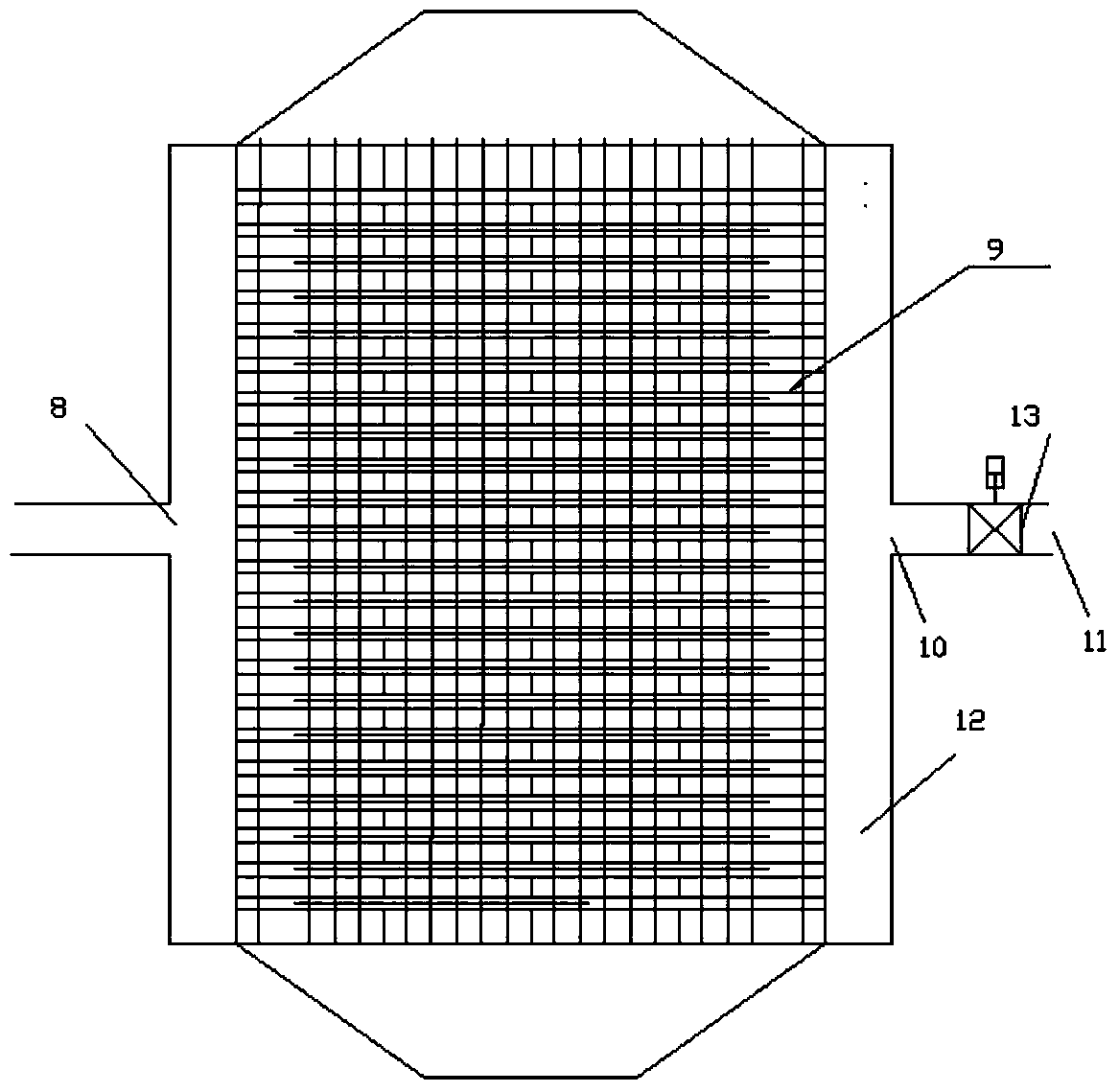
[0036] Such as figure 1 As shown, a regenerative heat exchanger for utilizing waste heat in the cement production process, the heat exchanger includes a heat storage material, a second hole 9, a high-temperature flue gas inlet 5, a high-temperature flue gas outlet 1, and a low-temperature working medium inlet 10 , a low-temperature working medium outlet 8 and a housing 2, the heat storage material is arranged in the housing, and the heat storage material is a solid heat storage material; a plurality of first holes 3 penetrating the heat storage material are arranged in the heat storage material With a plurality of second holes 9, the first hole 3 and the second hole 9 are intersected and not communicated with each other. The first hole 3 is used to circulate the flue gas produced in the cement production process, and the second hole 9 is used


PUM


Abstract

The invention provides a heat accumulating type heat exchanger for pipeless waste heat utilization in a cement manufacturing process. The heat exchanger comprises a heat accumulating material, a high-temperature flue gas inlet, a high-temperature flue gas outlet, a low temperature working medium inlet, a low temperature working medium outlet and a casing, wherein the heat accumulating material is arranged in the casing; the heat accumulating material is a solid heat accumulating material; a plurality of communicated first holes and a plurality of second holes of heat accumulating material are formed in the heat accumulating material; the first holes and the second hole are intercrossed but not communicated. According to the heat accumulating type heat exchanger, residual heat in the cement manufacture is fully utilized, the heat exchange efficiency is maximized, the energy is saved and the goals of environmental protection and energy conservation are achieved.

Description


Claims


Application Information

Patent Timeline
Owner 山东中和热工科技有限公司
Why Eureka
Try Eureka