Rolling bearing and associated mounting method

A rolling bearing and mounting surface technology, applied in shaft installation, roller bearings, bearing assembly, etc., can solve a large number of operations, reduce axial and radial forces and other problems, and achieve high mechanical strength

Inactive Publication Date: 2014-10-01
AB SKF
View PDF8 Cites 2 Cited by
  • Summary
  • Abstract
  • Description
  • Claims
  • Application Information

AI Technical Summary

Problems solved by technology

[0005] The presence of such sealing plugs in the load-bearing area of ​​rolling bearings causes the problem of reducing the permissible axial and radial fo

Method used


Image

  • Rolling bearing and associated mounting method
  • Rolling bearing and associated mounting method

Examples


Example Embodiment

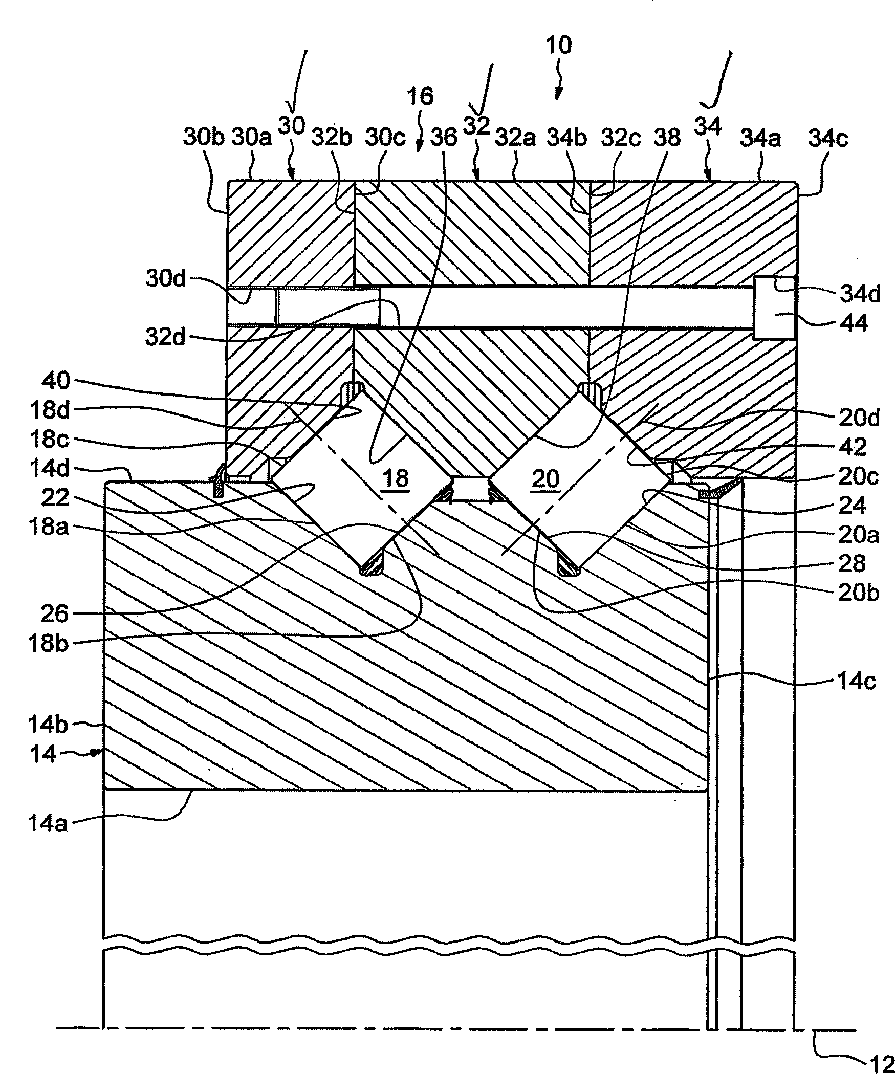
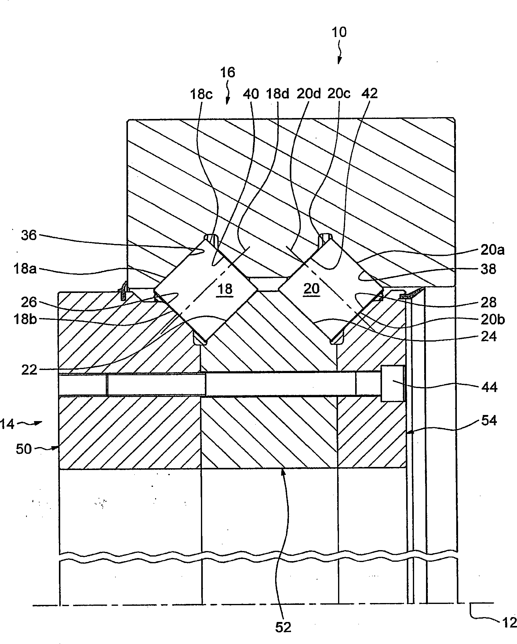
[0020] in figure 1 Medium and large-diameter rolling bearings 10 can be used especially for wind turbines or tunnel drilling rigs. The rolling bearing 10 has a shaft 12, including an inner ring 14, an outer ring 16, and two rows of angular contact rollers 18, 20 placed between the rings. The inner ring 14 and the outer ring 16 are coaxial and extend axially along the axis of rotation 12 of the bearing. The inner ring 14 is an integral ring. The term "integral ring" refers to a ring whose shape is obtained by machining, removing (turning, straightening) chips from pipes, bars, forging and / or rolling stocks. As will be explained in more detail below, the outer ring 16 is specially designed to facilitate the installation of the rollers 18, 20 in the radially defined annular space between the rings.

[0021] The rollers 18, 20 of the bearing are the same themselves, and each roller includes an outer rolling surface 18a, 20a and two opposite end surfaces 18b, 18c, 20b, 20c, which co


PUM


Abstract

The rolling bearing comprises an inner ring (14), an outer ring (16) and a plurality of rows of rolling elements (18, 20) each arranged between the raceways which are arranged on said rings, the number of rows of rolling elements N rows being in excess of or equal to two. At least one of the inner and outer rings (14, 16) comprises a plurality of part rings (30, 32, 34) which are mounted bearing axially against one another. The number of part rings N rings is defined by N rings N rows + 1.

Description


Claims


Application Information

Patent Timeline
Owner AB SKF
Why Eureka
Try Eureka