Improved welding mold for welding semiconductor power module

A technology of power modules and semiconductors, which is applied in the direction of semiconductor devices, welding equipment, auxiliary welding equipment, etc., can solve the problems of easy sliding, batch scrapping, etc., achieve the effect of less increase, less number of parts and cost, and guaranteed welding quality

Active Publication Date: 2014-12-10
XUZHOU HANTONG ELECTRONICS TECH CO LTD
View PDF5 Cites 8 Cited by
  • Summary
  • Abstract
  • Description
  • Claims
  • Application Information

AI Technical Summary

Benefits of technology

This innovation makes it easier for people who want to connect electronic components together by melting their own metal wire instead of relying on other methods like glue or adhesive tape. It also simplifies the process of connecting them with good results without adding extra steps compared to traditional ways such as screws or bolts.

Problems solved by technology

This patented technical problem addressed by this patents relates to improving the accuracy and consistency during electronic device manufacturing processes when applying solder onto specific areas with tiny differences between them (such as smaller chips).

Method used


Image

  • Improved welding mold for welding semiconductor power module
  • Improved welding mold for welding semiconductor power module

Examples


Embodiment Construction

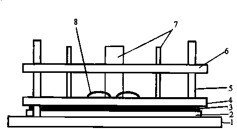
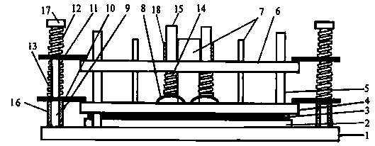
[0009] The invention provides an improved welding mold for welding semiconductor power modules. Describe below in conjunction with accompanying drawing.

[0010] figure 2 Shown is a schematic diagram of the improved welding mold structure. Vertically fix the uprights 9 at both ends or the periphery of the lengthened welding mold base 1, the uprights must be arranged symmetrically; the lower end of each upright 9 is first put on the backing ring 16, the backing ring 16 upper end is covered with the lower pressing plate 10, and the lower spring 13 is pressed Press the lower pressing plate 10, the upper pressing plate 11 presses the lower spring 13, the upper pressing plate 11 presses the upper spring 12, and the adjusting nut 17 is screwed on the upper end of each column 9; adjust the pressure of the upper and lower springs; the other of the upper and lower pressing plates One end presses the electrode positioning plate 6 and the chip positioning sheet 4 respectively, and welds


PUM


Abstract

The invention discloses an improved welding mold for welding a semiconductor power module and belongs to the field of tools and molds for manufacturing semiconductor power devices. The welding mold is obtained through improvement of an original welding mold, stand columns are vertically fixed to the two ends or the periphery of a lengthened welding mold base, the lower end of each stand column is sleeved with an upper backing ring, the upper end of each backing ring is sequentially sleeved with a lower pressing plate, a lower spring, an upper pressing plate and an upper spring, the other end of each upper pressing plate and the other end of each lower pressing plate press an electrode positioning plate and a chip positioning sheet respectively, and an adjusting nut is screwed onto the upper end of each stand column to adjust the pressure of the corresponding upper spring and the corresponding lower spring; each module electrode and each welding mold positioning stand column are sleeved with the electrode positioning plate, a gap bridge compression bar which can move up and down and is provided with a gap bridge compression spring is placed over each gap bridge, and each gap bridge compression bar is guided through a gap bridge compression bar guiding pipe. The welding mold is simple in structural design, practical, small in part number, low in cost increase, convenient to use, and capable of preventing deviation of the gap bridges when solder melts during welding, guaranteeing welding quality and improving the rate of finished products.

Description


Claims


Application Information

Patent Timeline
Owner XUZHOU HANTONG ELECTRONICS TECH CO LTD
Why Eureka
Try Eureka