Cyclone separator
A cyclone separator and separation cavity technology, applied in cyclone devices, devices with reversible cyclone axes, recycling technologies, etc., can solve the problem of increasing recycling costs and recycling efficiency, and the impact of dust content on the molding effect, etc. problems, to achieve the effect of improving the recovery rate and saving costs
- Summary
- Abstract
- Description
- Claims
- Application Information
AI Technical Summary
Problems solved by technology
Method used
Image

Examples
Example Embodiment
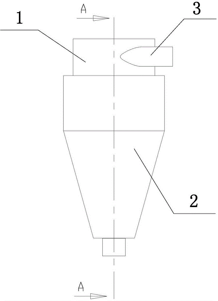
[0037] Example 1: See Figure 1 to Figure 4 .
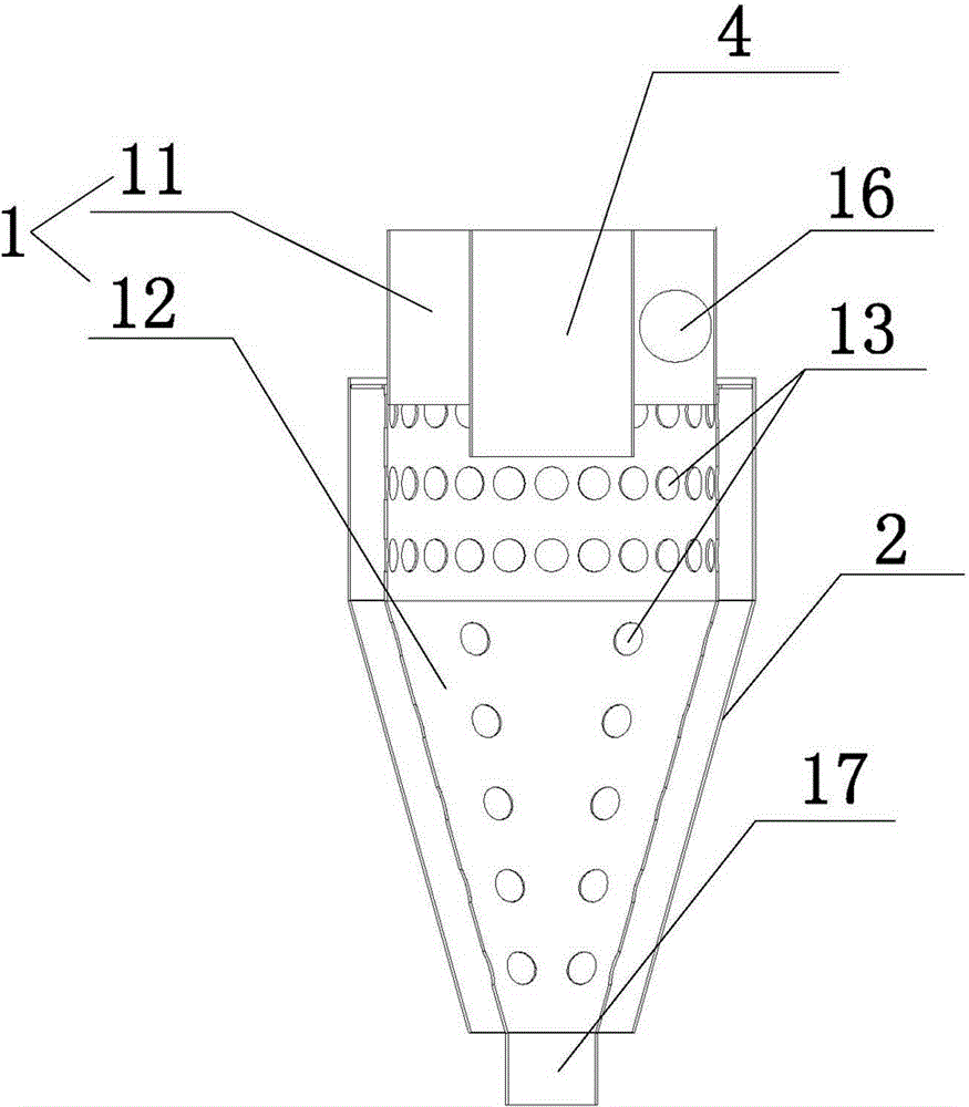
[0038] A cyclone separator, such as figure 1 , figure 2 Shown; including a separation cavity 1, the separation cavity 1 includes a first separation cavity 11 with a cylindrical cavity and a second separation cavity 12 with a cone-shaped cavity, the first separation cavity 11 is located in the first Above the second separation cavity 12, the side of the first separation cavity 11 is provided with a feed port 16, the feed port 16 is connected with a feed pipe 3, and the upper end of the first separation cavity 11 is connected with an exhaust pipe 4 and One end of the suction pipe 4 extends into the first separation cavity 11, a plurality of separation holes 13 are provided on the side of the first separation cavity 11, and a receiving cavity 2 is provided outside the separation cavity 1.
[0039] The cyclone separator can be used to separate smaller particles and dust in plastic waste; it can also further separate smaller particles of pl
Example Embodiment
[0046] Example 2: see Image 6 , Figure 8 , Picture 9 , A cyclone separator, its structure is different from embodiment 1 in that: the upper end of the separation hole 13 is provided with a guide cap 14, one end of the guide cap 14 is connected to the first separation cavity 11, the guide cap 14 The other end extends into the receiving cavity 2.
[0047] The guide cap 14 can be provided to introduce the separated matter into the receiving cavity. For example, when the particle size is separated, the smaller-volume particulate matter passes through the separation hole 13 and enters the receiving cavity 2 through the guide cap 14 to avoid the smaller volume. When the particles pass through the separation hole 13, they collide with the side surface of the separation hole 13. After a long time use, the separation hole 13 is deformed, reducing the separation rate, and the separation effect is poor. When the plastic particles are separated from the dust, it is also possible to prevent t
Example Embodiment
[0052] Example 3: A cyclone separator, see Picture 11 The difference between the structure and the embodiment 1 is that the separation holes 13 are distributed clockwise or counterclockwise.
[0053] When the separated matter passes through the separation hole 13, the separated matter advances at a tangential speed. In order to facilitate the separation of the separated matter along the guide cap 14 and reduce the collision between the separation hole 13 and the separated matter, the separation hole 13 can be set clockwise Or distributed counterclockwise, the length direction of the separation hole 13 is approximately the same or the same as the speed direction of the separated object.
[0054] Of course, the structure in Embodiment 2 can also be applied to Embodiment 3.
PUM
 Abstract
Description
Claims
Application Information
 - R&D Engineer
- R&D Manager
- IP Professional
- Industry Leading Data Capabilities
- Powerful AI technology
- Patent DNA Extraction
Browse by: Latest US Patents, China's latest patents, Technical Efficacy Thesaurus, Application Domain, Technology Topic.
© 2024 PatSnap. All rights reserved.Legal|Privacy policy|Modern Slavery Act Transparency Statement|Sitemap