Screw rod type impregnation equipment

A screw-type, dipping technology, applied in the direction of coating, etc., can solve the problems of damage to the health of operators, short fiber dipping time, insufficient dipping, etc., to achieve the effect of convenient observation, simple equipment, and good dipping effect

Active Publication Date: 2015-07-01
SHANDONG UNIV
View PDF4 Cites 4 Cited by
  • Summary
  • Abstract
  • Description
  • Claims
  • Application Information

AI Technical Summary

Benefits of technology

This technology solves problems by avoiding exposure to harmful chemicals during the process while also improves efficiency compared to traditional methods like immersion or spray drying techniques. It uses an enclosed system where only one part goes into the gluing material instead of another, resulting in longer contact times without contamination from any external sources. Additionally, it provides a way to measure how well this method works effectively when used on materials that have different levels of moisture content (such as paper).

Problems solved by technology

This patented technical problem addressed by this patents relates to improving the efficient use of dips during production processes for reinforce plastic material products such as carbon fiberglass pipes or other similar items made from synthetic polymeric composites (SCPC). Current methods are slow and require excessive amounts of liquid glues due to their high viscosity. Additionally, these techniques have potential negative effects on workers' wellbeing when they come near them while pouring liquids onto surfaces like glass windows.

Method used

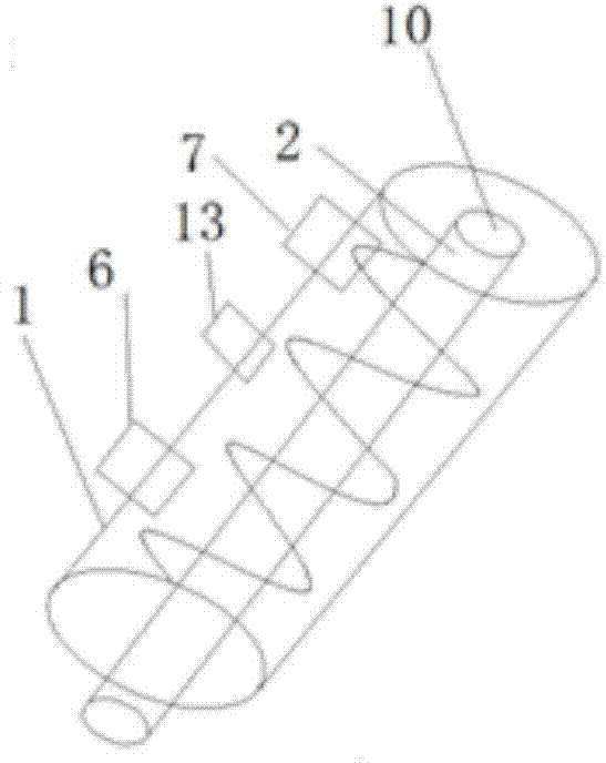
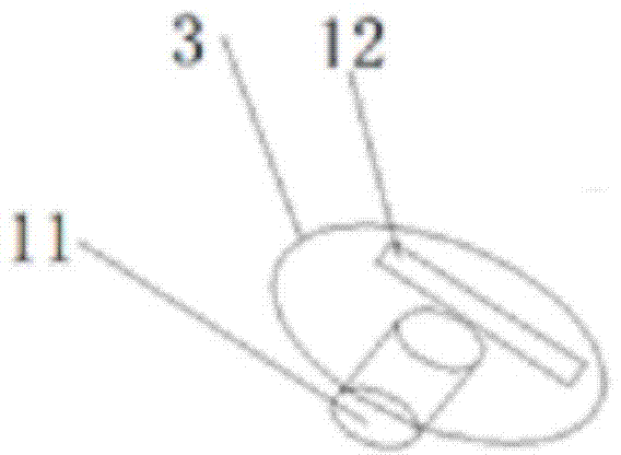
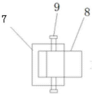

Image

  • Screw rod type impregnation equipment
  • Screw rod type impregnation equipment
  • Screw rod type impregnation equipment

Examples


Embodiment 1

[0034] Take 0030 bundles of T700-12K carbon fiber dipped in epoxy resin with a viscosity of 3000mps as an example.

[0035] The dipping sleeve 1 and the dipping shaft 2 are made of 304 stainless steel. Insert 30 bundles of T700-12K carbon fiber through the tow inlet 7, wind them on the dipping shaft 2 according to the thread direction, and pass them out from the tow exit 6 after winding. The thread section of the dipping shaft 2 is trapezoidal, and wrap the Put the dipping shaft 2 of good carbon fiber into the dipping sleeve 1, insert one end of the dipping shaft 1 into the first cylindrical hole 10, align the second cylindrical hole 11 with the other end of the dipping shaft 2, and then cover the dipping sleeve Canister cover 3. Place the installed dipping sleeve 1 on the support 4. The insulation cover 5 is heated by a carbon fiber electric heater, and the insulation temperature is set at 40°C. Pour epoxy resin from the injection port 13. Observe the height of the glue in t

Embodiment 2

[0037] Take 50 bundles of 12K glass fibers dipped in phenolic resin with a viscosity of 7000mps as an example.

[0038] The dipping sleeve 1 and the dipping shaft 2 adopt polytetrafluoroethylene. Put 50 bundles of 12K glass fiber through the tow inlet 7, wind it on the dipping shaft 2 according to the thread direction, and pass it out from the tow outlet 6 after winding. The cross section of the thread is triangular. Put the shaft 2 into the dipping sleeve 1, insert one end of the dipping shaft 2 into the first cylindrical hole 10, align the second cylindrical hole 11 with the other end of the dipping shaft 2, and then cover the dipping sleeve cover 3. Place the installed dipping sleeve 1 on the support 4. The heat preservation cover 5 adopts the water heat preservation of setting temperature through the interior, and the heat preservation temperature is set to 60 ℃. Pour the phenolic resin from the injection port 13. Observe the height of the glue in the dipping sleeve 1 from


PUM


Abstract

The invention relates to screw rod type impregnation equipment which comprises an impregnation sleeve, an impregnation shaft arranged inside the impregnation sleeve in a sleeving manner, and a glue injection hole, a tows inlet and a tows outlet which are formed in the same side of the impregnation sleeve, wherein the tows inlet and the tows outlet are respectively positioned in the left and right ends of the impregnation sleeve; the impregnation shaft is a screw rod type impregnation shaft; the threaded length of the impregnation shaft is smaller than the length of the impregnation sleeve; glue solution is poured from the glue injection hole, the sizes of the tows inlet and the tows outlet can be adjusted by virtue of an adjusting block and a fastening bolt, the condition that net one strand of tows enters the impregnation sleeve is ensured by adjusting the size of the tows inlet, and the glue content of fibers separated from the impregnation sleeve after impregnation is controlled by adjusting the size of the tows outlet. The screw rod type impregnation equipment disclosed by the invention is closed impregnation equipment, the glue solution is not contacted with outer atmosphere, and pollution is avoided; screw rod type impregnation is adopted, the tows totally enter the glue solution, the contact time with the glue solution is long, full impregnation is realized, and the impregnation effect is good.

Description


Claims


Application Information

Patent Timeline
Owner SHANDONG UNIV
Why Eureka
Try Eureka