Hydraulic geotextile bag dewatering box

A dehydration box and geotechnical bag technology, applied in the direction of dehydration/drying/concentrated sludge treatment, etc., can solve the problems of difficult on-site operation, pollution, and low dehydration efficiency, so as to reduce secondary pollution, shorten operation time, and improve dehydration efficiency Effect

Inactive Publication Date: 2015-08-26
天津市海顺交通工程设计有限公司 +1
View PDF8 Cites 2 Cited by
  • Summary
  • Abstract
  • Description
  • Claims
  • Application Information

AI Technical Summary

Benefits of technology

This patented technology allows for efficient cleanup on large bodies of water such as lakes or rivers through an apparatus called GE bags that are placed near these locations during excavations. These devices help remove sediment from the surface while still allowing fluids like oil and gas to pass freely into their own reservoir without contamination. By doing so they have potential benefits over traditional methods where there're always going back after being done with dirty tools.

Problems solved by technology

This patented technical solution described by this patents relates to improving the quality control (QC) process performed at locales where sediment from streams can accumulate over time without being treated properly. Current methods involve removing contaminant containing material through physical means like bags that require heavy lifting equipment and may lead to environmental concerns.

Method used


Image

  • Hydraulic geotextile bag dewatering box
  • Hydraulic geotextile bag dewatering box

Examples


Embodiment 1

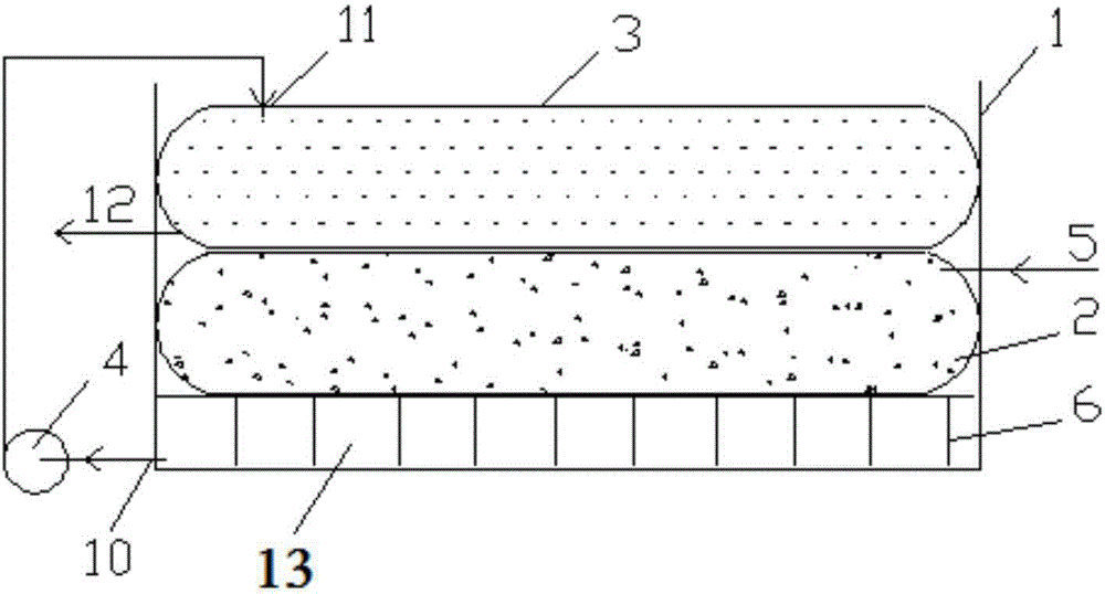
[0015] Such as figure 1 As shown, the dehydration box 1 is placed on a flat and relatively hard ground or platform, and the seepage pool 13 is formed between the platform brackets arranged at the bottom of the dehydration box 1, and the dehydration bag 2 is placed on the bracket 6 at the bottom of the box body 1, and then Put the hydraulic bag 3 flat on the dehydration bag 2, then connect the mud injection port 5 of the dehydration bag, and pass the pipeline and the water pump 4 between the water injection port 11 of the hydraulic bag and the water outlet 10 of the seepage tank 13 connect. When working, first inject the slurry to be dehydrated into the dewatering bag 2 through the mud injection port 5, and during the pouring process, water will continuously escape into the seepage pool 13 at the bottom of the box body 1, and start the water pump 4 to collect this part of the dehydrated water from the water outlet 10 And inject it into the water pressure bag 3 through the water i

Embodiment 2

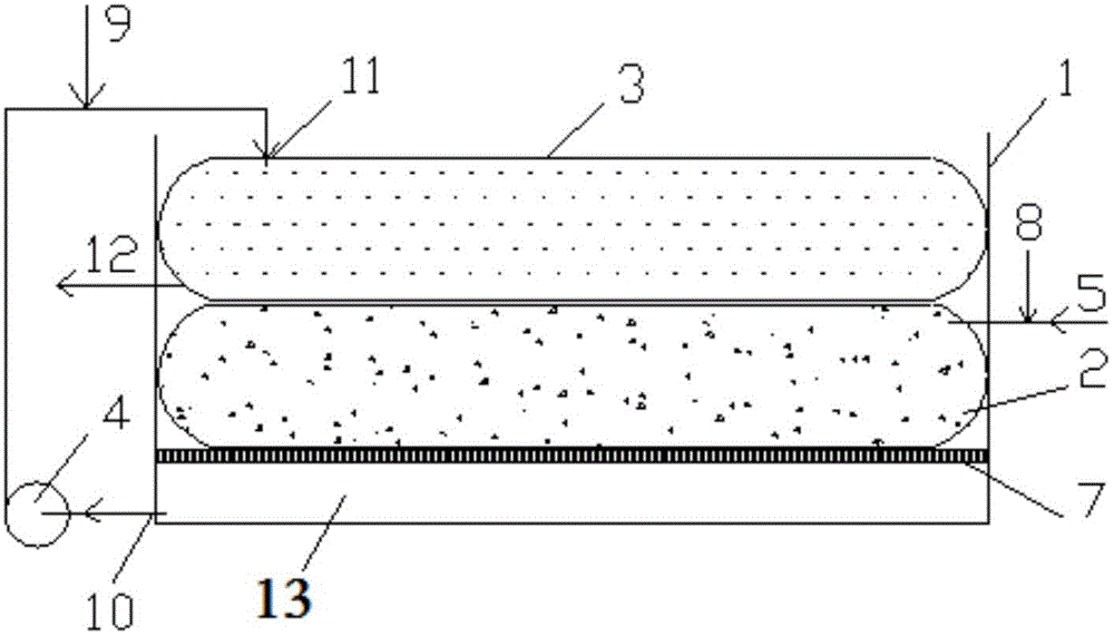
[0017] Such as figure 2 As shown, the dehydration box is placed on a flat and relatively hard ground or platform, and the seepage pool 13 is formed between the partitions arranged at the bottom of the dehydration box 1, and the dehydration bag 2 is placed on the partition 7 at the bottom of the box body 1, and then Put the hydraulic bag 3 flat on the dehydration bag 2, then connect the mud injection port 5 of the dehydration bag, and pass the pipeline and the water pump 4 between the water injection port 11 of the hydraulic bag and the water outlet 10 of the seepage tank 13 connect. Connect dehydration agent 8 (polyferric sulfate, etc.) to the mud injection pipeline, and connect water purification agent 9 (polyaluminum chloride, etc.) to the pipeline at the rear end of the water pump. When working, first inject the mud to be mixed with dehydrating agent into the dehydration bag 2 through the mud injection port 5, during the pouring process, water will continuously escape into t


PUM


Abstract

The invention relates to a hydraulic geotextile bag dewatering box. A water seepage tank is formed among platform brackets or separator plates arranged on the bottom layer of the dewatering box; a dewatering bag is flat laid on the platform brackets or the separator plates; a hydraulic bag is flat laid on the dewatering bag; a mud injection opening is formed in the dewatering bag; a water inlet is formed in the hydraulic bag; a water outlet is formed in the water seepage tank; the water inlet of the hydraulic bag is connected with the water outlet of the water seepage tank through a pipe and a water pump. The dewatering box can complete the dewatering process on the water desilting site, and can effectively solve the transport and subsequent disposal problems caused by high moisture content of sludge. According to the invention, the dewatering effect of the geotextile bag is strengthened by using the dewatering box body and the hydraulic function, and the equipment structure and dewatering process are described; the method and equipment can effectively improve the dewatering efficiency of the geotextile bag, reduce the operation time, effectively improve the quality of separated water, and reduce the secondary pollution; the equipment can also be used for dewatering sewage sludge, building mud, bean dregs and other materials.

Description


Claims


Application Information

Patent Timeline
Owner 天津市海顺交通工程设计有限公司
Why Eureka
Try Eureka