Shoe washing machine

A technology for a shoe washing machine and an inner cylinder is applied in the field of shoe washing machines, which can solve the problems of time-consuming, laborious, and numb arms of shoes, and achieve the effects of reasonable structure, lightening of housework, and improving quality of life.

Active Publication Date: 2015-10-07
赵延江
View PDF8 Cites 0 Cited by
  • Summary
  • Abstract
  • Description
  • Claims
  • Application Information

AI Technical Summary

Problems solved by technology

Scrubbing shoes by hand is not only time-consuming, but also very laborious. If you wash two

Method used


Image

  • Shoe washing machine
  • Shoe washing machine
  • Shoe washing machine

Examples


Example Embodiment

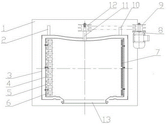
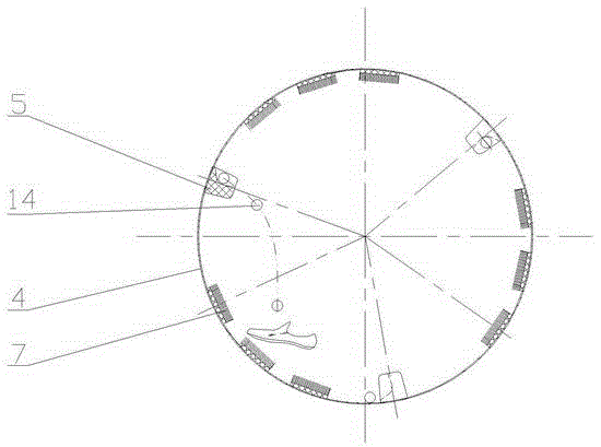
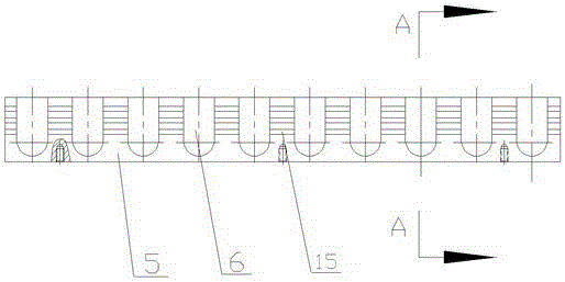
[0008] A shoe washing machine, such as figure 1 , figure 2 , image 3 , Figure 4 As shown, a horizontal outer cylinder 3 provided with inlet and outlet pipes 2, 10 is installed on the supporting device 1, and an inner cylinder 4 with a rotating shaft 11 and a supporting pipe is installed in the outer cylinder 3 through a bearing. The wall of the cylinder body is uniformly provided with water passage holes, and the pulley 12 is installed on the inner cylinder shaft 11 that extends out of the outer cylinder 3. The inner cylinder 4 of the inner cylinder 4 is uniformly spaced and arranged in a staggered arrangement on the circumferential surface of the inner cylinder wall. The brush row group and the conveying plate 5, in which the length of the brush row 7 of the brush row group is adapted to the length of the inner cylinder 4. The structure of the conveying plate 5 is that it is horizontally uniformly arranged on the long support 14 is the matching conveying channel 6, the directi


PUM

PropertyMeasurementUnit
Diameteraaaaaaaaaa

Abstract

The invention discloses a shoe washing machine. A horizontal type outer barrel with a water inlet pipe and a water outlet pipe is installed on a supporting device, and an inner barrel with a rotating shaft and a bearing pipe is installed in the outer barrel through a bearing in a matched manner; water through holes are evenly distributed on the wall of the inner barrel, and a belt pulley is installed at the portion, extending out of the outer barrel, of the rotating shaft of the inner barrel; row brush sets and conveying plates which are alternatively arranged at intervals are evenly arranged on the circumferential face of the inner wall of the inner barrel in the longitudinal direction, and the length of row brushes of the row brush sets is matched with the length of the inner barrel; the structure of the conveying plate is characterized in that conveying ways matched with patting balls are evenly arranged on a long-strip-shaped support transversely, and the moving direction of the conveying ways is perpendicular to the axis of the inner barrel; and the patting balls are installed in the inner barrel, a loading and unloading opening with a sealing door is arranged at the end, with the bearing pipe, of the inner barrel, and the loading and unloading opening extends out from a matching opening on an end wall of the outer barrel. The shoe washing machine is reasonable in structure, shoes can be washed and rinsed at a time, people can be liberated from time-wasting manual brushing work, housework is relieved, and the life quality of people is improved.

Description


Claims


Application Information

Patent Timeline
Owner 赵延江
Why Eureka
Try Eureka