Memory integrity protection method based on write counter

An integrity protection and counter technology, applied in the direction of digital data protection, etc., can solve the problems of large time delay, long tree mechanism verification path, etc., and achieve the effect of low verification cost

Active Publication Date: 2015-11-18
HARBIN ENG UNIV
View PDF4 Cites 13 Cited by
  • Summary
  • Abstract
  • Description
  • Claims
  • Application Information

AI Technical Summary

Problems solved by technology

[0004] The disadvantage of the tree mechanism is that the verif

Method used


Image

  • Memory integrity protection method based on write counter
  • Memory integrity protection method based on write counter
  • Memory integrity protection method based on write counter

Examples


Embodiment Construction

[0028] The present invention will be further described below in conjunction with the accompanying drawings.

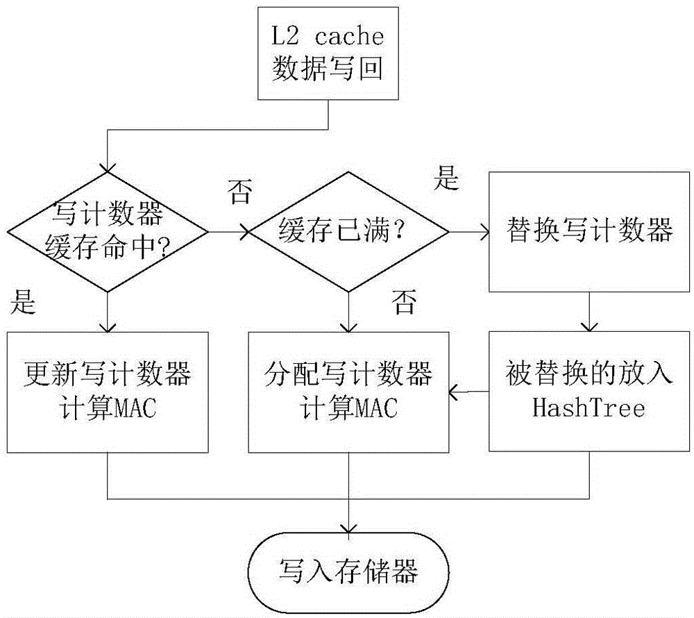
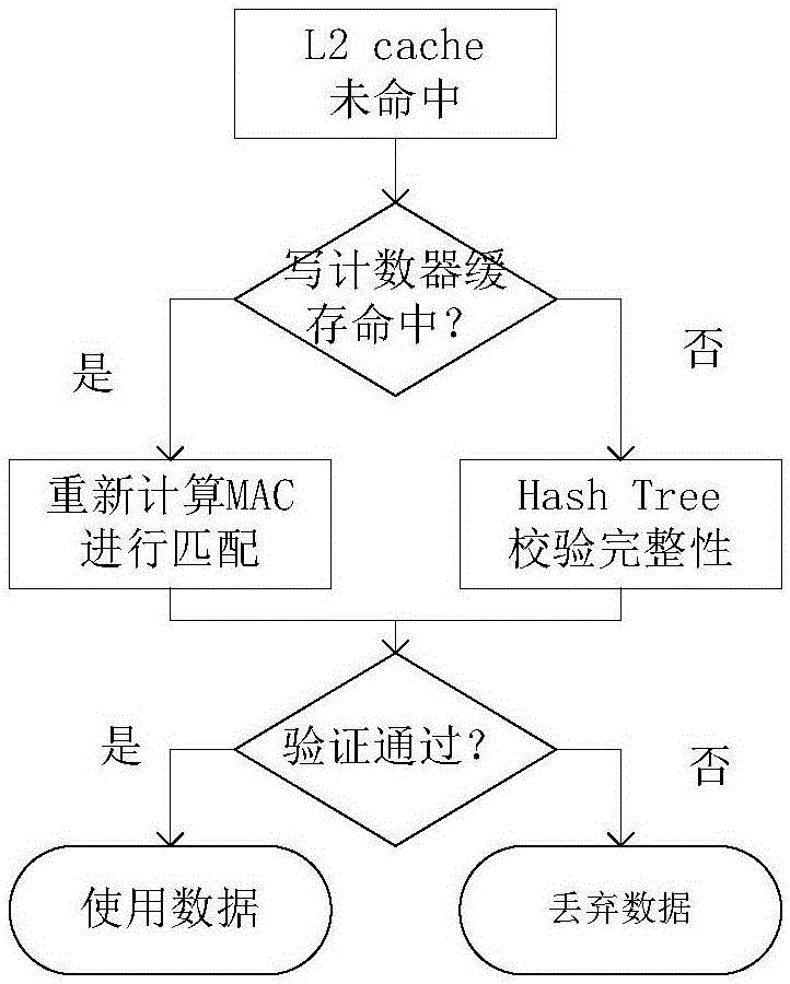
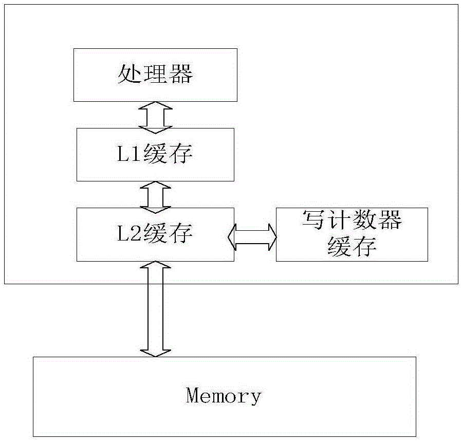
[0029] The invention relates to the field of memory integrity verification, in particular to a memory integrity protection method based on a write counter. At present, tree structures such as MerkleTree, PAT, and TEC-Tree are mainly used in memory integrity to protect memory. When updating data, it needs to recurse from the leaf node to the root node, and the delay is very large. The present invention adopts different integrity verification mechanisms for the data on the memory. A data block has a write counter, which is used to record the number of times the processor writes to the address memory block. When writing data, the memory block address, write counter and data content are connected, and then the MAC function is calculated to obtain the corresponding authentication label for completeness. Integrity verification; some data blocks do not have write counters, and


PUM


Abstract

The present invention relates to the field of memory integrity verification, in particular to a memory integrity protection method based on a write counter. According to the memory integrity protection method based on the write counter, two types of data blocks are provided, the corresponding write counter is provided for one type of data blocks and is used for recording the number of writing times of a processor to an address memory block, the write counter is stored in a specific write counter cache in a processor chip, and the write counter cache is located on the same level as an L2 cache; and in the write counter cache, a private key is also assigned for the data blocks. Compared to adoption of a hash check tree, adoption of a message verification code for performing integrity verification has the largest advantage of much lower verification cost. When the integrity verification is performed by using the hash check tree, iteration needs to be carried out from a leaf node to a root node to calculate a hash value; but for the message verification code, MAC calculation only needs to be carried out for once, i.e. only one layer of operations in the hash tree needs to be performed.

Description


Claims


Application Information

Patent Timeline
Owner HARBIN ENG UNIV
Why Eureka
Try Eureka