Metal automatic grinding seal device

A sealing device, automatic technology, applied in the direction of engine sealing, engine components, mechanical equipment, etc., to achieve the effect of long service life, reduced maintenance times and maintenance costs

Inactive Publication Date: 2015-11-25
CHENGDU NINGJIA HONGFU TECH CO LTD
View PDF5 Cites 1 Cited by
  • Summary
  • Abstract
  • Description
  • Claims
  • Application Information

AI Technical Summary

Problems solved by technology

[0003] Based on the above background, the purpose of the present invention is to solve the problem that the existing air sealing device cannot 100% ensu

Method used


Image

  • Metal automatic grinding seal device

Examples


Embodiment Construction

[0010] The present invention will be further described below in conjunction with the accompanying drawings and specific embodiments.

[0011] In order to make the object, technical solution and advantages of the present invention clearer, the present invention will be further described in detail below in conjunction with the accompanying drawings and embodiments. It should be understood that the specific embodiments described here are only used to explain the present invention, not to limit the present invention.

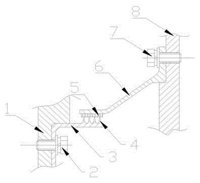
[0012] like figure 1 as shown, one A metal automatic running-in sealing device, including a rotor assembly 1, a sealing tooth 3, a sealing ring 6, and a stator assembly 8, wherein the sealing tooth 3 is provided with four tooth tips 4, and the tooth tips 4 are sprayed with high temperature resistant The grinding material body; the sealing ring 6 is provided with a honeycomb 5, and when working, the tooth tip 4 cuts into the honeycomb 5 to form a sealing fit.

[001


PUM


Abstract

The invention discloses a metal automatic grinding seal device. The metal automatic grinding seal device comprises a rotor assembly (1), a seal labyrinth (3), a seal ring (6) and a stator assembly (8) and is characterized in that a plurality of tooth tips (4) are arranged on the seal labyrinth (3), a high-temperature-resistant and wear-resistant material body is sprayed on the tooth tips (4), a honeycomb (5) is arranged on the seal ring (6), and during work, the tooth tips (4) extend into the honeycomb (5) so as to form seal fit. According to the invention, four tooth tips are arranged on the seal labyrinth, the high-temperature-resistant, wear-resistant and high-hardness material is sprayed on the tooth tips, when the rotor assembly rotates at a high speed, the diameters of the tooth tips are increased under the action of centrifugal force, and at the same time, the tooth tips grind the honeycomb, extend into the honeycomb and form close fit with the honeycomb, so that a great seal effect is played. As the seal components, such as the tooth tips and the honeycomb, are all made of high-temperature alloy, the service life of the seal device is longer, and later maintenance times and maintenance fees are also greatly reduced.

Description


Claims


Application Information

Patent Timeline
Owner CHENGDU NINGJIA HONGFU TECH CO LTD
Why Eureka
Try Eureka