Manufacturing method for high-speed permanent magnetic rotor

A permanent magnet rotor and manufacturing method technology, applied in the manufacture of stator/rotor body, etc., can solve problems such as potential safety hazards, and achieve the effect of meeting the requirements of high-speed use

Inactive Publication Date: 2015-12-23
HARBIN DONGAN ENGINE GRP
View PDF3 Cites 5 Cited by
  • Summary
  • Abstract
  • Description
  • Claims
  • Application Information

AI Technical Summary

Benefits of technology

This patented technology describes an improved design used on electric motors with strong cores. It uses iron powder mixed with aluminum oxide (Al 2 O 3) or other materials like ceramic material instead of traditional binders such as epoxy resin. These improvements help improve performance over existing designs without compromising their overall effectiveness under certain conditions.

Problems solved by technology

This patented technical problem addressed in the patents relates to improving the performance of an electric machine that uses a conventional type of permanent magnet (PM) rotor design without causing any harm or injury from it when operated at speeds above 10 million rounds per minute.

Method used


Image

  • Manufacturing method for high-speed permanent magnetic rotor

Examples


Embodiment Construction

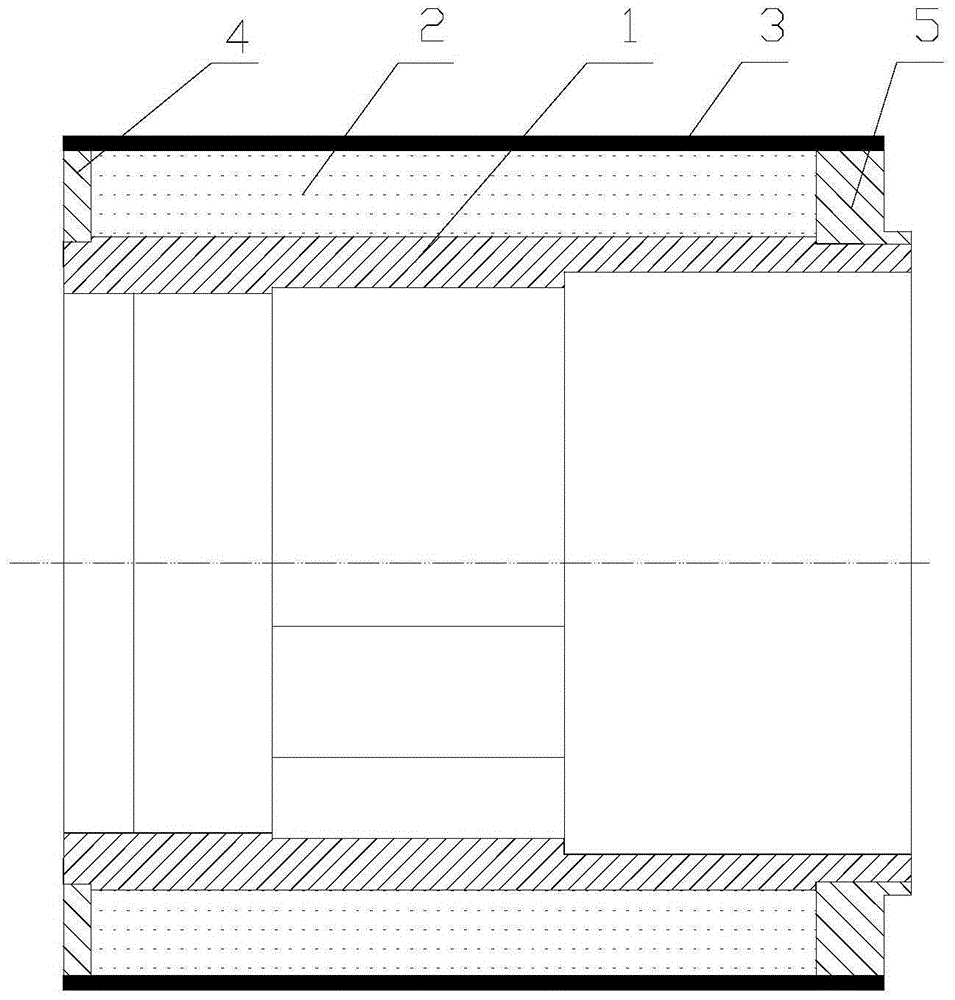
[0016] As shown in the figure, the manufacturing method of the high-speed permanent magnet rotor includes the following steps:

[0017] (1) Processing: Process the permanent magnet pole 2, left baffle plate 4, right baffle plate 5, rotor core 1, and thin-walled sheath 3 to the requirements of the drawing, among which the permanent magnet pole 2 is a sintered permanent magnet pole ;

[0018] (2) Install the left baffle: press-fit the left baffle 4 onto the rotor core 1, the press-fit interference is between 0.04mm and 0.05mm, and then follow the requirements of the C-level standard in GB / T22085.2 Laser welding the two into one;

[0019] (3) Install the magnetic poles: use TS812 high-temperature structural adhesive to pair the magnetic poles according to different polarities, and bond the counterweight to the rotor core 1, and fill the gap with TS812 high-temperature structural adhesive and then cure. The curing time is 32 to 40 hours;

[0020] (4) Install the right baffle plat


PUM

PropertyMeasurementUnit
Weld widthaaaaaaaaaa
Depthaaaaaaaaaa
Thicknessaaaaaaaaaa

Abstract

The invention relates to a manufacturing method for a high-speed permanent magnetic rotor. By performing the processes of assembling, polishing, dynamic balance and the like, and setting reasonable parameters, it can be ensured that magnetic poles of the motor rotor are firmly bonded on a rotor iron core at a high speed of 40,000 rpm. The permanent magnetic rotor manufactured with the method can work under a condition that the rotational speed is 50,000 rpm for a long term, is successfully applied to power motors of digital electronic control systems of aircraftengines, and meets operating requirements of high rotational speeds of aviation motors.

Description


Claims


Application Information

Patent Timeline
Owner HARBIN DONGAN ENGINE GRP
Why Eureka
Try Eureka