Solar battery bus bar bending device

A technology of solar cells and bending devices, which is applied to circuits, photovoltaic power generation, electrical components, etc., can solve the problems of low welding efficiency, easy to generate welding bumps, and many welding procedures, and achieve convenient operation, less processing procedures, and high efficiency. high effect

Inactive Publication Date: 2016-03-23
SUZHOU BOYANG ENERGY EQUIP
View PDF3 Cites 2 Cited by
  • Summary
  • Abstract
  • Description
  • Claims
  • Application Information

AI Technical Summary

Benefits of technology

This technology allows for direct bending of long conductors like those used by older methods such as welding or soldering without requiring multiple steps that are time-consuming processes. It also makes it easier to use while still being effective at transmitting signals effectively over longer distances.

Problems solved by technology

This patented technical problem addressed in the patents relates to improving the production rate at which solar panelling technology becomes commercially viable while also addressing concerns related to reducing greenhouse gases (GH) pollution caused by coal use.

Method used


Image

  • Solar battery bus bar bending device
  • Solar battery bus bar bending device
  • Solar battery bus bar bending device

Examples


Embodiment

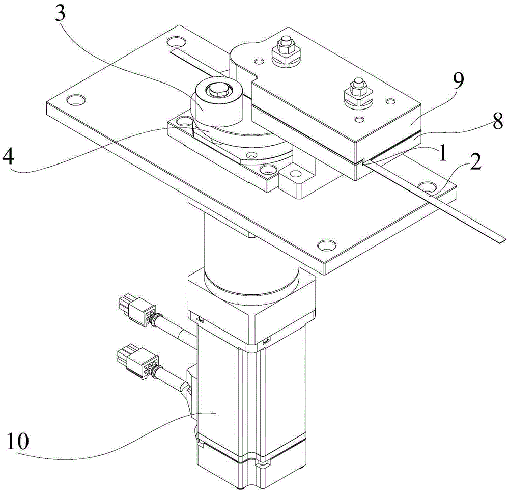
[0024] Example: solar cell bus bar bending device

[0025] See attached Figure 1~6 As shown, the solar cell bus bar bending device includes a bus bar supply groove 1 for the bus bar to pass through, and the side part corresponding to the bus bar supply groove 1 is provided with a bus current in the bus bar supply groove 1. The rolling roller 3 pressed by the bar 2 is rotatably supported on the eccentric shaft of an eccentric mechanism, and the rotating shaft of the eccentric mechanism is connected with the output shaft of a driving device 10 through transmission. The eccentric mechanism of the present embodiment is specifically an eccentric wheel mechanism, specifically, the rolling roller 3 is rotatably supported on the eccentric shaft of the eccentric wheel 4 of the eccentric wheel mechanism, and the rotating shaft of the eccentric wheel 3 is connected to the output shaft of the driving device 10 through a transmission drive. The device 10 may be a hydraulic motor or an elect


PUM


Abstract

The invention relates to a solar battery bus bar bending device. The solar battery bus bar bending device includes a bus bar supply groove through which a bus bar can pass, and a pressing roller which is corresponding to the side portion of the bus bar supply groove and applies pressure to the bus bar in the bus bar supply groove; the pressing roller is rotationally supported on the eccentric shaft of an eccentric mechanism; and the rotation shaft of the eccentric mechanism is in transmission connection with the output shaft of a driving device. According to the solar battery bus bar bending device of the invention, an elongated bus bar can be directly bent into an L-shaped bus bar. The solar battery bus bar bending device has the advantages of few processing steps, convenient operation and high efficiency.

Description


Claims


Application Information

Patent Timeline
Owner SUZHOU BOYANG ENERGY EQUIP
Why Eureka
Try Eureka