Dual-layer mechanical grate type garbage gasifying incinerator and dual-boiler power generation system thereof

A technology of mechanical grate and power generation system, which is applied in the direction of mechanical equipment, machine/engine, incinerator, etc. It can solve the problem that the heat energy recovery system and flue gas treatment system are greatly affected, and the continuous gasification incineration treatment and ash cleaning of garbage cannot be realized. Overhaul and maintenance period is short and other problems, to achieve the effect of improving energy conversion efficiency, improving heat exchange efficiency, and ensuring thermal ignition loss rate

Active Publication Date: 2016-04-06
CHONGQING SANFENG ENVIRONMENTAL IND GRP +1
View PDF8 Cites 5 Cited by
  • Summary
  • Abstract
  • Description
  • Claims
  • Application Information

AI Technical Summary

Benefits of technology

Inventions described include an improved design for a coal oxide (CO) firing facility called LFT® Stack Gasifiers or GUDG Bidirectional Combined Cyclast Incubbery Intermediate Furnaces (SCIFE). These designs aim to efficiently treat wastes while reducing environmental impact such as nitrogen compounds, sulfur dioxides, carbon monoxies, hydrocarbon chlorine products, volatile organic solids, heavy metallurgical scrap materials, and particulate matter produced due to incomplete combusted zones within the kilns' internal passages. By combining these features, efficient operation, recirculative combustor systems, closed loop combustors, and advanced cycle units have been developed. Additionally, there may incorporates various components like pipelines, valves, and equipment to further enhance their functionality.

Problems solved by technology

This patented describes different methods or techniques related to treatments involving municipal wastes including both burning and non-incidential dispositions. These new approaches aim towards better management of these wastes by increasing resource reuse while minimizing negative effects associated with traditional means. Additionally, they require efficient processing systems to achieve effective separation and purifying of harmful components without causing contamination issues themselves.

Method used


Image

  • Dual-layer mechanical grate type garbage gasifying incinerator and dual-boiler power generation system thereof
  • Dual-layer mechanical grate type garbage gasifying incinerator and dual-boiler power generation system thereof
  • Dual-layer mechanical grate type garbage gasifying incinerator and dual-boiler power generation system thereof

Examples


Embodiment Construction

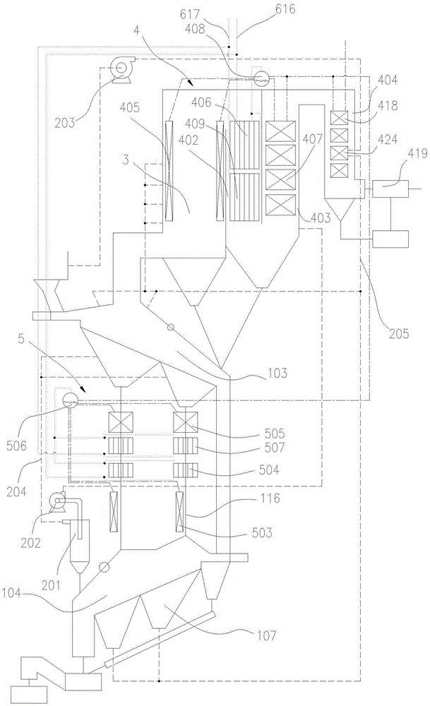
[0051] See Figure 1 to Figure 6 , Is a preferred embodiment of a double-layer mechanical grate type waste gasification incinerator and its double boiler power generation system, including a double-layer waste gasification incinerator 1, a boiler system, a circulating air supply system, and a power generation system.

[0052] See Image 6 , Including a double-layer garbage gasification incinerator 1, the double-layer garbage gasification incinerator 1 includes a grate 101 on which a feeding bin 102 and a gasification furnace 103 are sequentially arranged along the feeding direction. The furnace frame 101 is also provided with an incinerator 104. The incinerator 104 is located directly below the gasification furnace 103. The feeding direction of the incineration furnace 104 is opposite to that of the gasification furnace 103. 103 is mainly to gasify the charcoal part of the garbage and discharge combustible gasification flue gas and garbage residue. The incinerator 104 mainly performs


PUM


Abstract

The invention discloses a dual-layer mechanical grate type garbage gasifying incinerator and a dual-boiler power generation system thereof. The dual-layer mechanical grate type garbage gasifying incinerator comprises a dual-layer garbage gasifying incinerator, a boiler system and a circulating air supply system, wherein the dual-layer garbage gasifying incinerator comprises a feeding hopper, a gasification furnace and a burnout furnace; the burnout furnace is positioned directly under the gasification furnace; the feeding direction of the burnout furnace is opposite to the feeding direction of the gasification furnace, and flue gas outlets are formed in the upper end of the gasification furnace and the upper end of the burnout furnace; the boiler system comprises a boiler body a, and a boiler body b, wherein the boiler body a is provided with a cyclone-combustion chamber, a furnace chamber a, and a furnace chamber b; a flue gas inlet of the cyclone-combustion chamber is connected with a flue gas outlet of the gasification furnace; the boiler body b is provided with evaporators b, superheaters b, and water-cooled walls b, which are arranged on a flue gas pipeline in a sleeving manner, wherein the superheaters are arranged in the furnace chamber a, the evaporators are arranged in the furnace chamber b, and the superheaters and the evaporators are arranged in a furnace chamber d; steam drums are arranged at the top ends of the two boiler bodies.

Description


Claims


Application Information

Patent Timeline
Owner CHONGQING SANFENG ENVIRONMENTAL IND GRP
Why Eureka
Try Eureka