Antitheft backpack with multiple conductive materials being embedded into zipper teeth
A technology of conductive materials and chain teeth, applied in the field of packaging, can solve the problems of insufficient functions, inability to keep pace with the times, and low ability to combine anti-theft performance.
- Summary
- Abstract
- Description
- Claims
- Application Information
AI Technical Summary
Problems solved by technology
Method used
Image

Examples
Embodiment 1
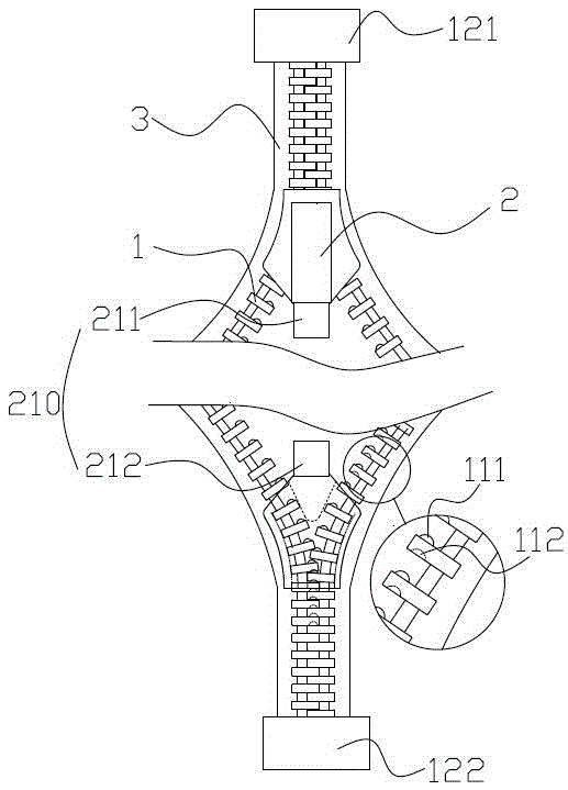
[0030] like Figure 1~2 As shown, each chain tooth is made of conductive material or its surface is electroplated with conductive substance. Two opposite first zipper pullers and second zipper pullers are arranged on the chain tape. When the two zipper pullers are respectively in the When the two ends are at the two ends, the two chains are separated. When the two chains are separated, all the chain teeth are separated from each other, so the zipper is in a disconnected state. , so that the chain teeth passing through the zipper head mesh with each other to form a whole in contact with each other. Since the chain teeth themselves are plated with conductive substances or made of conductive materials, the current can be conducted on the mutually meshed chain teeth. As the two zipper pulls approach gradually, the length of the zipper that can be conducted becomes larger and larger, and when the two zipper pulls are in contact with each other, the length of the zipper that can be con
Embodiment 2
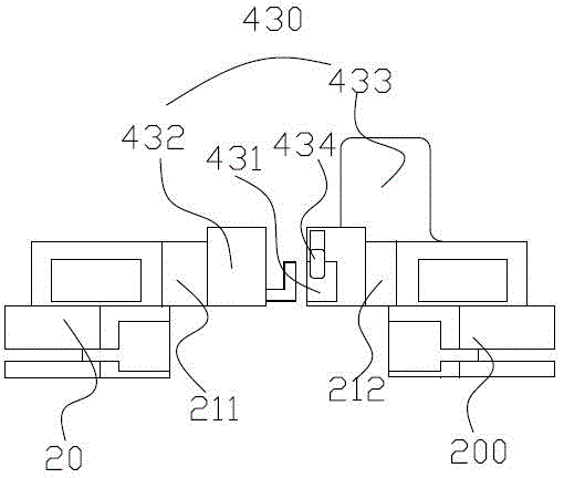
[0037] The difference between this embodiment and embodiment 1 is that, as image 3shown. The sprocket is composed of a conductive part and an insulating part, and the sprocket includes a sprocket end connected with a chain belt and a sprocket front end for interlocking with other sprockets. Wherein, the front end of the sprocket is a conductive part, and the end of the sprocket is an insulating part. The front end of the sprocket and the end of the sprocket can be designed in one piece, or the front end of the sprocket can be connected to the end of the sprocket by inlaying. This structure can limit the current to the center of the zipper, reducing the probability of voltage and current changes due to the contact between the chain teeth and other objects.
[0038] Correspondingly, the elastic protrusions of the zipper slider are arranged at the positions corresponding to the front ends of the chain teeth.
Embodiment 3
[0040] The difference between this embodiment and embodiment 1 is that, as Figure 4 and Figure 5 shown. The sprocket is composed of a conductive part and an insulating part, wherein the conductive part is wrapped by the insulating part. Preferably, the sprocket made of conductive material is the conductive part, and the insulating material wrapped on the sprocket forms the insulating part. At the same time, the insulating part is connected to the chain belt, so that the chain teeth are fixed on the chain belt. In order to ensure the conduction of the circuit, the contact protrusions and contact recesses of the chain teeth are not covered with insulating materials, so that the conductive materials at the front ends of two adjacent chain teeth can contact each other. In addition, in order to realize the electrical connection between the chain teeth and the slider, grooves are formed on the bottom surface of the ends of the chain teeth, and the bottom of the grooves is not cove
PUM
 Abstract
Description
Claims
Application Information
 - R&D Engineer
- R&D Manager
- IP Professional
- Industry Leading Data Capabilities
- Powerful AI technology
- Patent DNA Extraction
Browse by: Latest US Patents, China's latest patents, Technical Efficacy Thesaurus, Application Domain, Technology Topic.
© 2024 PatSnap. All rights reserved.Legal|Privacy policy|Modern Slavery Act Transparency Statement|Sitemap