System, method and device for writing in charging zone bit and mobile terminal
A charging flag and mobile terminal technology, which is applied in electrical digital data processing, instruments, etc., can solve the problems of USB interface occupation and inability to write charging flags in mobile terminals.
- Summary
- Abstract
- Description
- Claims
- Application Information
AI Technical Summary
Problems solved by technology
Method used
Image

Examples
Example Embodiment
[0032] Example one
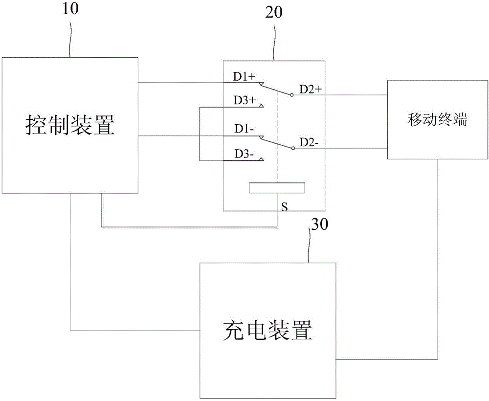
[0033] figure 1 It is a schematic structural diagram of a system for writing charging flag bits according to Embodiment 1 of the present invention. See figure 1 The system for writing the charging flag bit provided by this embodiment specifically includes:
[0034] The control device 10, the switch circuit 20, the charging device 30, and the mobile terminal; the switch circuit 20 includes a first channel, a second channel, and a third channel; wherein the third channel includes a USB connection with the mobile terminal Each data port of the interface corresponds to the line, and each line is short-circuited;
[0035] The control device 10 is connected to the first channel, the second channel is connected to the data port of the USB interface of the mobile terminal, and the power port of the charging device 30 is connected to the power port of the USB interface;
[0036] Wherein, the USB interface includes two data ports, and each channel of the switch circuit 20 inc
Example Embodiment
[0045] Example two
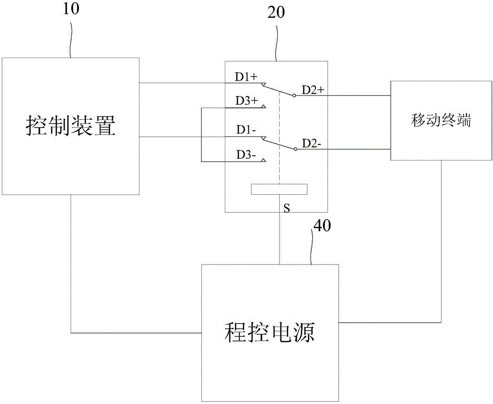
[0046] figure 2 It is a schematic structural diagram of a system for writing charging flag bits according to the second embodiment of the present invention. This embodiment is based on the first embodiment above, and the charging device is an implementation of a program-controlled power supply.
[0047] See figure 2 On the basis of the above-mentioned implementation 1, the switch circuit 20 further includes a switch selection port; the command output terminal of the programmable power supply 40 is connected to the switch selection port of the switch circuit 20;
[0048] The control device 10 is specifically configured to: after obtaining the test result of the charging function of the mobile terminal, instruct the programmable power supply 40 to send a trigger signal to the switch circuit 20 through the command output terminal, and the switch circuit 20, according to the trigger signal received at the switch selection port, disconnect the path between the second
Example Embodiment
[0052] Example three
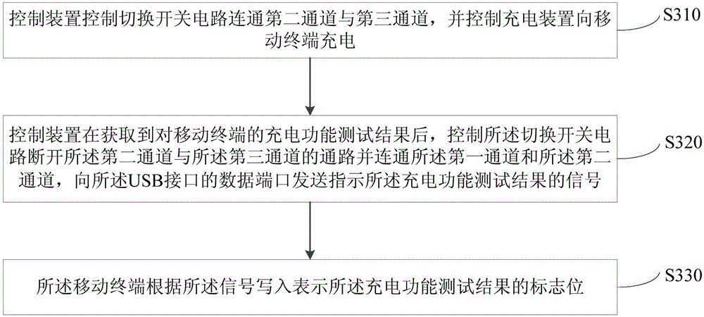
[0053] image 3 It is a schematic flowchart of a method for writing a charging flag bit according to the third embodiment of the present invention. The method can be executed by the system in the first embodiment or the second embodiment, see image 3 The method for writing a flag bit provided by this embodiment specifically includes:
[0054] S310. The control device controls the switch circuit to connect the second channel and the third channel, and controls the charging device to charge the mobile terminal;
[0055] S320. After obtaining the test result of the charging function of the mobile terminal, the control device controls the switch circuit to disconnect the path between the second channel and the third channel and connect the first channel and the second channel. Channel, sending a signal indicating the result of the charging function test to the data port of the USB interface;
[0056] The signal of the charging function test result sent by the control
PUM
 Abstract
Description
Claims
Application Information
 - R&D Engineer
- R&D Manager
- IP Professional
- Industry Leading Data Capabilities
- Powerful AI technology
- Patent DNA Extraction
Browse by: Latest US Patents, China's latest patents, Technical Efficacy Thesaurus, Application Domain, Technology Topic.
© 2024 PatSnap. All rights reserved.Legal|Privacy policy|Modern Slavery Act Transparency Statement|Sitemap