Gate system automatically controlled to be in position

A technology for controlling gates and gates, applied in water conservancy projects, marine engineering, coastline protection, etc., can solve problems such as excessive lifting and cumbersome operation, and achieve the effects of reasonable design, convenient use and simple structure

Inactive Publication Date: 2016-08-10
浙江禹川勘测设计有限公司
View PDF7 Cites 4 Cited by
  • Summary
  • Abstract
  • Description
  • Claims
  • Application Information

AI Technical Summary

Problems solved by technology

[0002] At present, the lifting gates in the prior art are manually placed in place, that is, when the gate is opened and closed, the staff must be on site, and two or more people need to operate at the same time, one person controls the switch, and one person observes and When operating the door rest, the observer needs to promptly report the gate situation to the operator during the specific operation
Therefore, not only is the operation cumbersome, but also there are manual errors, and excessive lifting and falling back occur from time to time

Method used


Image

  • Gate system automatically controlled to be in position
  • Gate system automatically controlled to be in position
  • Gate system automatically controlled to be in position

Examples


Example Embodiment

[0016] The present invention will be further described below in conjunction with the drawings.

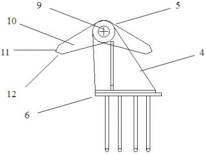
[0017] Such as Figure 1-Figure 4 As shown, this embodiment describes a gate system with automatic control in place, which includes a gate 1, a power mechanism that controls the up and down movement of the gate 2, a gate groove 3 that cooperates with the gate, and an automatic door rest; the power mechanism 2 is a hoist. The said automatic door shelf includes a locking frame 4 and a locking block 5. The locking frame 4 is fixed on a base 6 with two opposing plates 7, and the corresponding positions of the plates 7 are provided with holes. 8. The connection between the locking block 5 and the locking frame 4 is realized by the pin 9 passing through the hole 8 on the plate and the central hole on the locking block 5. The locking block 5 can rotate freely around the pin; the locking block 5 is obtusely angled It is composed of a symmetrical base plate 10, and a central hole through which t


PUM


Abstract

The invention relates to a gate system, in particular to a gate system capable of being automatically controlled in place. It includes the gate, the power mechanism that controls the up and down movement of the gate, the gate slot that matches the gate, and the automatic door rest; the side of the gate is in contact with the locking block of the automatic gate rest, and when the gate moves from the bottom up, it is driven to be close to it. One end of the locking block rotates upward around the pin, and an inverted L-shaped positioning block is fixed on the contact surface between the side of the gate and the locking block. When the gate rises to a high point, the inverted L-shaped positioning block cooperates with the end of the locking block. To achieve the function of shelving the gate; the two sides of the base plate of the locking block at 90° cooperate with the inverted L-shaped positioning block; the power mechanism is connected to the gate, and the power mechanism is equipped with a controller, which controls the gate to rise or fall. Therefore, it has the characteristics of simple structure, reasonable design and convenient use.

Description


Claims


Application Information

Patent Timeline
Owner 浙江禹川勘测设计有限公司
Why Eureka
Try Eureka