Bridge connecting mechanism for brick stacking

A technology of connecting bridges and bricks, which is applied in the field of bricks and bridges, which can solve the problems of low production efficiency and manpower consumption, and achieve the effect of guaranteed effect, reduced labor intensity and good consistency

Active Publication Date: 2016-08-31
ZIYANG JINGGONG MECHANICS
View PDF9 Cites 1 Cited by
  • Summary
  • Abstract
  • Description
  • Claims
  • Application Information

AI Technical Summary

Benefits of technology

The technology described in this patented method allows for easier manual handling during manufacturing processes without requiring excessive effort from people working with them. This results in improved productivity while maintaining quality control standards over time.

Problems solved by technology

This patented technical problem addressed by this patents relates to improving the efficient use of labor resources for producing high-quality ceramic products while ensuring proper alignment between different layers within each layer after they have been fired from an initial state onto another support material called greenware or other substrate used with the final product.

Method used


Image

  • Bridge connecting mechanism for brick stacking
  • Bridge connecting mechanism for brick stacking
  • Bridge connecting mechanism for brick stacking

Examples


Embodiment 1

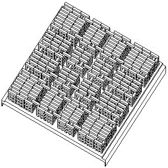
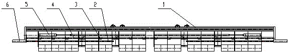
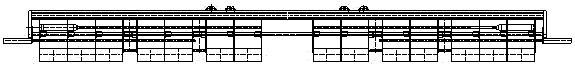
[0019] A bridge mechanism for stacking bricks, comprising a main frame 1, a pulling shaft 2, a linear bearing 3, a clamping shaft 4, a brick clamping cylinder 5 and a brick pulling cylinder 6, the clamping shaft 4 is fixedly connected under the main frame 1, and the Several groups of clamping plates are also arranged below the main frame 1, and the distance rods are fixedly connected between each group of clamping plates, and each clamping plate is installed on the clamping shaft 4 through a linear bearing 3 and horizontally sliding, and the pulling shaft 2 One end passes through each group of clamping plates horizontally and is fixed, the other end is connected with the output rod of the brick pulling cylinder 6, and the brick pulling cylinder 6 is fixedly arranged under the main frame 1, and the output end of the brick clamping cylinder 5 is connected through the connecting rod. lengthen, and then the two ends are fixedly connected with the outermost clamping plates of the sever

Embodiment 2

[0023] Such as figure 1 As shown, a brick-connecting bridge mechanism includes a main frame 1, a pulling shaft 2, a linear bearing 3, a clamping shaft 4, a brick clamping cylinder 5 and a brick pulling cylinder 6, and the clamping shaft 4 is fixedly connected under the main frame 1 , several groups of clamping plates are also arranged under the main frame 1, each group of clamping plates is fixedly connected by distance rods, and each clamping plate is installed on the clamping shaft 4 through a linear bearing 3 and horizontally slidable, so that One end of the pulling shaft 2 passes through each group of clamping plates horizontally and is fixed, and the other end is connected with the output rod of the brick pulling cylinder 6. The brick pulling cylinder 6 is fixedly arranged under the main frame 1, and the output end of the brick clamping cylinder 5 passes through the The connecting rod is lengthened, and then the two ends are fixedly connected with the outermost clamping plat


PUM


Abstract

The invention discloses a bridge connecting mechanism for brick stacking. The bridge connecting mechanism for brick stacking comprises a main frame, a pulling shaft, linear bearings, a clamping shaft, a brick clamping air cylinder and a brick pulling air cylinder. The clamping shaft is fixedly connected to the lower portion of the main frame. A plurality of sets of clamping plates are further arranged below the main frame. All the sets of clamping plates are fixedly connected through spacing rods. Each clamping plate is horizontally and slidably installed on the clamping shaft through the corresponding linear bearing. One end of the pulling shaft horizontally penetrates through all the sets of the clamping plates and is fixed, and the other end of the pulling shaft is connected with an output rod of the brick pulling air cylinder. The brick pulling air cylinder is fixedly arranged below the main frame. The output end of the brick clamping air cylinder is lengthened through a connecting rod, and then the two ends of the brick clamping air cylinder are fixedly connected with the outermost clamping plates of the sets of clamping plates. The bridge connecting mechanism for brick stacking has the beneficial effects that the bridge connecting mechanism can be used in the process of brick pulling and bridge connecting of green bricks in a brickyard, manual brick pulling and bridge connecting are replaced, the labor intensity of workers is relieved, and the production efficiency is improved; and in addition, the brick pulling and bridge connecting effect is guaranteed, the consistency is good, and influences of human factors are few.

Description


Claims


Application Information

Patent Timeline
Owner ZIYANG JINGGONG MECHANICS
Why Eureka
Try Eureka