Steel ball mounting machine with bearing holding frame

A technology of bearing cage and cage, which is applied in the field of bearing assembly, can solve problems such as low production efficiency, unsatisfactory efficiency, and high labor intensity, and achieve the effects of high production efficiency, simple and reasonable structure, and light labor intensity

Active Publication Date: 2017-02-01
江苏持华科技有限公司
View PDF15 Cites 3 Cited by
  • Summary
  • Abstract
  • Description
  • Claims
  • Application Information

AI Technical Summary

Benefits of technology

This patented technology allows for easy installation or replacement of bearings on equipment without requiring expensive machinery that requires skilled workers with specialized training. It also makes it easier than previous methods due to its simplicity and ease-of-use design.

Problems solved by technology

This patented method involves manual filling with small steel balls onto an axle bearing during manufacturing processes that require multiple steps such as extrusion or pressing for added strength. These technical problem addressed by this technology include increased costs associated with these procedures while also requiring more time than necessary because it requires two separate operations - one step before another when making sure there's no interference between them (extruding) and another afterward step where they can be pressed together again afterwards.

Method used


Image

  • Steel ball mounting machine with bearing holding frame
  • Steel ball mounting machine with bearing holding frame
  • Steel ball mounting machine with bearing holding frame

Examples


Embodiment Construction

[0031] The technical solutions in the embodiments of the present invention will be clearly and completely described below. Obviously, the described embodiments are only a part of the embodiments of the present invention, rather than all the embodiments. Based on the embodiments of the present invention, all other embodiments obtained by those of ordinary skill in the art without creative efforts shall fall within the protection scope of the present invention.

[0032] see Figure 1 to Figure 9 , the embodiments of the present invention include:

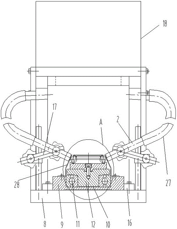
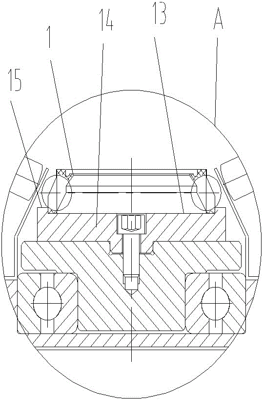
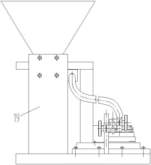
[0033] like Figure 1 to Figure 8 As shown, a bearing cage steel ball installation machine includes: a cage rotation device, at least one guide ball hard tube and a steel ball supply device.

[0034] The cage rotating device is used to carry the cage 1 and drive the cage to rotate. Specifically, the holder rotating device includes a base 8, a carriage 9 is placed above the base, a groove 10 is formed in the middle of the carriage, and


PUM


Abstract

The invention discloses a steel ball mounting machine with a bearing holding frame. The steel ball mounting machine comprises a holding frame rotating device used for bearing the holding frame and driving the holding frame to rotate, at least one ball guide hard tube and a steel ball supply device, wherein a ball outlet in the tail end of the ball guide hard tube is opposite to the edge of the holding frame; the ball guide hard tube has a gradient for automatically rolling a steel ball; when a ball pocket of the holding frame rotates to the ball outlet, the steel ball automatically drops into the ball pocket of the holding frame; the tail end of the ball guide hard tube is sequentially divided into a front tube wall region, a tube center and a rear tube wall region in the rotation direction of the holding frame; the rear tube wall region is equipped with a convex extrusion part relative to the front tube wall region; when the ball pocket with the steel ball continuously rotates towards the rear tube wall region from the tube center, the convex extrusion part provides pressure for completely pressing the steel ball into the ball pocket; and the steel ball supply device is used for supplying the steel ball into the ball guide hard tube. In this way, the steel ball mounting machine has the characteristics of low manufacturing cost, simple operation, light labor intensity, high production efficiency and a wide product applicable range.

Description


Claims


Application Information

Patent Timeline
Owner 江苏持华科技有限公司
Why Eureka
Try Eureka