Uv-curable resin composition for use in touchscreen, and bonding method and article using said uv-curable resin
A curable resin, touch panel technology, applied in non-polymer organic compound adhesives, adhesive methods, adhesive types, etc., can solve problems such as high volatility, insoluble analysis, and component ratio changes
- Summary
- Abstract
- Description
- Claims
- Application Information
AI Technical Summary
Problems solved by technology
Method used
Image

Examples
no. 1 approach
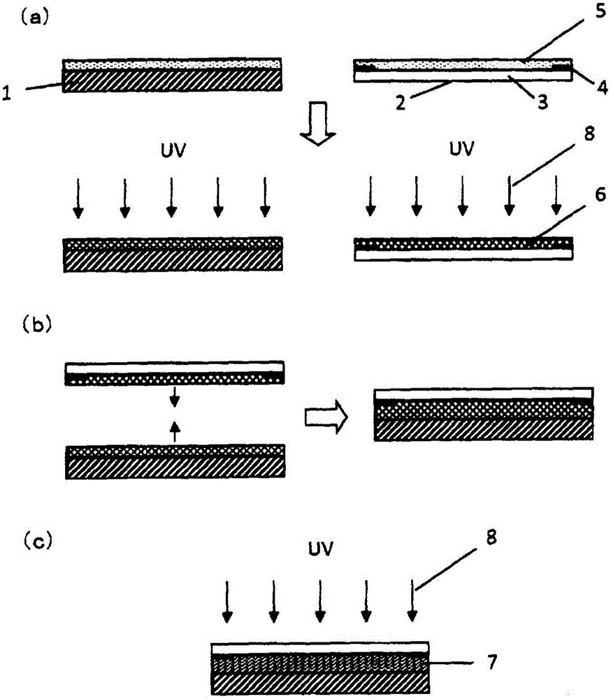
[0126] figure 1 It is a process drawing which shows 1st Embodiment of the manufacturing process of the optical member using the ultraviolet curable resin composition of this invention.
[0127] This method is a method of obtaining an optical member by bonding the liquid crystal display unit 1 and the transparent substrate 2 together.
[0128] The liquid crystal display unit 1 is a liquid crystal display unit in which a liquid crystal material is sealed between a pair of substrates on which electrodes are formed, and includes a polarizing plate, a driving circuit, a signal input cable, and a backlight unit.
[0129] The transparent substrate 2 is a glass plate, polymethyl methacrylate (PMMA) plate, polycarbonate (PC) plate, alicyclic polyolefin polymer (COP) plate, acrylic resin, polyethylene terephthalate and other transparent substrates. For transparent substrates, hard coat treatment and anti-reflection treatment can be performed on one or both sides.
[0130] Here, as the t
no. 2 approach
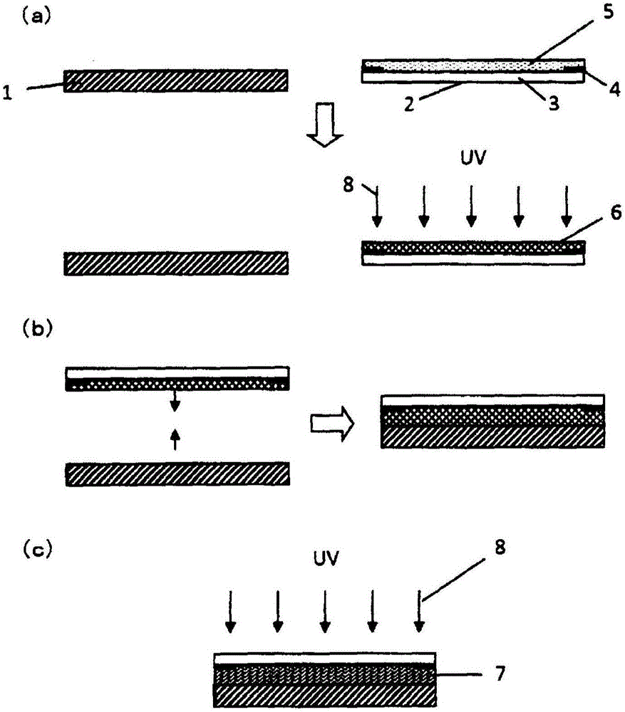
[0154] The optical member of the present invention can also be produced by the second embodiment modified as follows from the first embodiment. In addition, the same content as the said 1st Embodiment applies to the detailed content in each process, Therefore, description about the same part is abbreviate|omitted.
[0155] (Process 1)
[0156] First, if figure 2 As shown in (a), the ultraviolet curable composition is applied to the surface on which the light shielding portion 4 is formed on the transparent substrate 2 having the light shielding portion, and then the resulting coating layer (ultraviolet curable resin composition layer 5) UV rays 8 are irradiated to obtain a cured portion present on the lower side of the coating layer (viewed from the above ultraviolet curable resin composition, the transparent substrate side) and a cured portion present on the upper side of the coating layer (opposite to the transparent substrate side). Cured material layer 6 of the uncured par
no. 3 approach
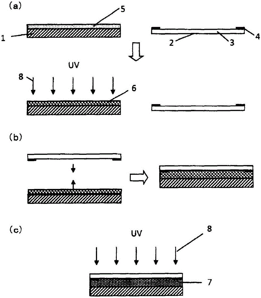
[0164] image 3 It is a process drawing which shows 3rd Embodiment of the manufacturing method of the optical member using the ultraviolet curable resin composition of this invention. In addition, the same content as the said 1st Embodiment applies to the detailed content in each process, Therefore, description about the same part is abbreviate|omitted.
[0165] In addition, the same code|symbol is attached|subjected to the same member in the said 1st Embodiment as a constituent member in the said figure, and the description is not repeated here.
[0166] (Process 1)
[0167] First, if image 3 As shown in (a), the ultraviolet curable composition is coated on the surface of the liquid crystal display unit 1 . Then, ultraviolet rays 8 are irradiated to the ultraviolet curable resin composition layer 5 to obtain a cured portion existing on the lower side of the coating layer (viewed from the above ultraviolet curable resin composition, the transparent substrate side) and a cured
PUM
| Property | Measurement | Unit |
|---|---|---|
| Thickness | aaaaa | aaaaa |
Abstract
Description
Claims
Application Information
 - R&D Engineer
- R&D Manager
- IP Professional
- Industry Leading Data Capabilities
- Powerful AI technology
- Patent DNA Extraction
Browse by: Latest US Patents, China's latest patents, Technical Efficacy Thesaurus, Application Domain, Technology Topic.
© 2024 PatSnap. All rights reserved.Legal|Privacy policy|Modern Slavery Act Transparency Statement|Sitemap