Anti-explosion LNG thermal insulation tank

A technology for thermal insulation tanks and cold tanks, which is applied in the method of container discharge, container filling method, gas/liquid distribution and storage, etc., can solve the problems of storage tank explosion, adverse personal and property safety, easy to cause explosion, etc., to avoid injury. Effect

Active Publication Date: 2017-06-06
ZHEJIANG OCEAN UNIV
View PDF4 Cites 0 Cited by
  • Summary
  • Abstract
  • Description
  • Claims
  • Application Information

AI Technical Summary

Benefits of technology

This new type of insulated container solves problems associated with traditional liquefied natural gas (LN) tanks used for transportation or storage purposes due to their high risk of being easily ignited during accidents such as fires causing injury or loss of life. It also prevents accidental fire hazards from occurring when there are no flammable liquids inside it without any safety concerns related to its use.

Problems solved by technology

The technical problem addressed in this patented text relates to preventing leaks from storing liquefiable gases like methane (LNG) due to its high risk during transportation or accidental spills caused by small cracks on top.

Method used


Image

  • Anti-explosion LNG thermal insulation tank
  • Anti-explosion LNG thermal insulation tank

Examples


Embodiment

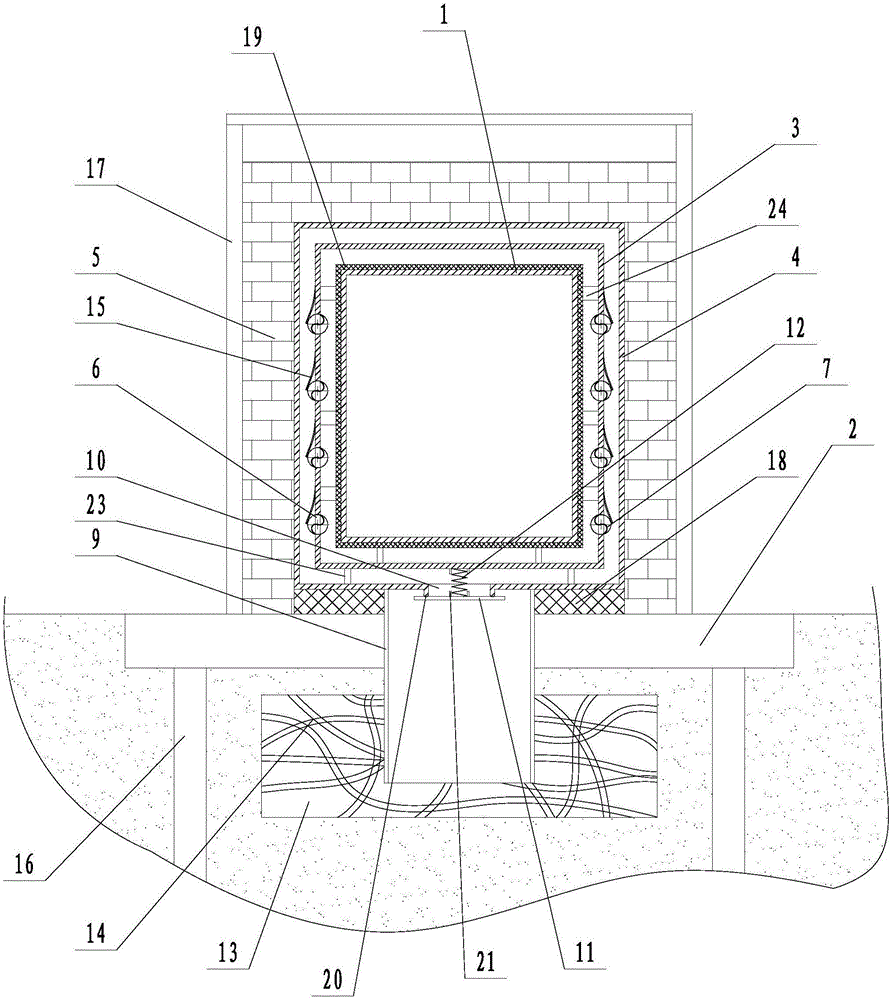
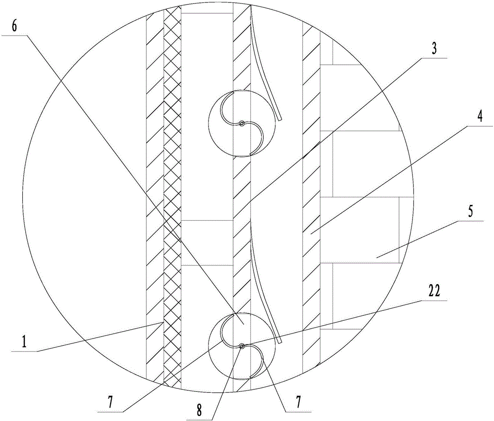
[0017] Embodiment: a kind of explosion-proof LNG insulation tank (see attached figure 1 , attached figure 2 ), including a cold storage tank 1, an installation platform 2, a buffer cylinder 3 and a closed cylinder 4 are arranged on the outside of the cold storage tank in turn, and a protective wall 5 is arranged outside the closed cylinder, and the protective wall is arranged on the installation platform. The cold storage tank body and the There is a gap between the buffer cylinders and between the buffer cylinder and the closed cylinder. The lower end of the cold insulation tank is connected to the bottom of the buffer cylinder through the connecting column 23, and the lower end of the buffer cylinder is connected to the bottom of the closed cylinder through the connecting column. A plurality of connection blocks 24 are connected between the outer wall of the cold storage tank and the inner wall of the buffer cylinder. A number of air holes 6 are arranged on the side wall of t


PUM


Abstract

The invention discloses an anti-explosion LNG thermal insulation tank. The anti-explosion LNG thermal insulation tank aims to solve the problems that after LNG cold preservation tanks are leaked, explosion is easily caused, and the human body and the property are greatly damaged. The anti-explosion LNG thermal insulation tank comprises a cold preservation tank body and an installation table, a buffer cylinder and a closed cylinder are sequentially arranged on the outer side of the cold preservation tank body, a plurality of air holes are formed in the side wall of the buffer cylinder, S-shaped rotating blades are rotatably connected in the air holes, the upper half parts of the rotating blades protrude inwards in an arc mode, the ends of the upper half parts of the rotating blades are close to the inner edges of the upper ends of the air holes, the lower half parts of the rotating blades protrude outwards in an arc mode, the ends of the lower half parts of the rotating blades are close to the outer edges of the lower ends of the air holes, the lower end of the closed cylinder is tightly connected with an exhaust pipe, an exhaust hole communicating with the exhaust pipe is formed in the lower end of the closed cylinder, a sealing disc covers the lower end of the closed cylinder and tightly covers the outer end of the exhaust hole, a pull spring is connected between the sealing disc and the lower end of the buffer cylinder, a buffer pit is formed in the ground below the installation table, the lower end of the exhaust pipe extends to the bottom of the buffer pit, and buffer branches are buried in the buffer pit.

Description


Claims


Application Information

Patent Timeline
Owner ZHEJIANG OCEAN UNIV
Why Eureka
Try Eureka