Panel switch

A flat switch and switch unit technology, applied in the direction of electric switches, electrical components, circuits, etc., can solve the problems of waste of resources, safety, hidden dangers, etc., and achieve the effect of preventing safety hazards and saving power

Inactive Publication Date: 2017-07-18
合肥梦飞电器有限公司
View PDF5 Cites 0 Cited by
  • Summary
  • Abstract
  • Description
  • Claims
  • Application Information

AI Technical Summary

Problems solved by technology

[0003] The invention proposes a panel switch, which solves the problems of resource waste a

Method used


Image

  • Panel switch
  • Panel switch

Examples


Example Embodiment

[0020] The technical solutions in the embodiments of the present invention will be clearly and completely described below with reference to the accompanying drawings in the embodiments of the present invention. Obviously, the described embodiments are only a part of the embodiments of the present invention, but not all of the embodiments. Based on the embodiments of the present invention, all other embodiments obtained by those of ordinary skill in the art without creative efforts shall fall within the protection scope of the present invention.

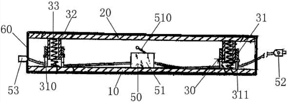
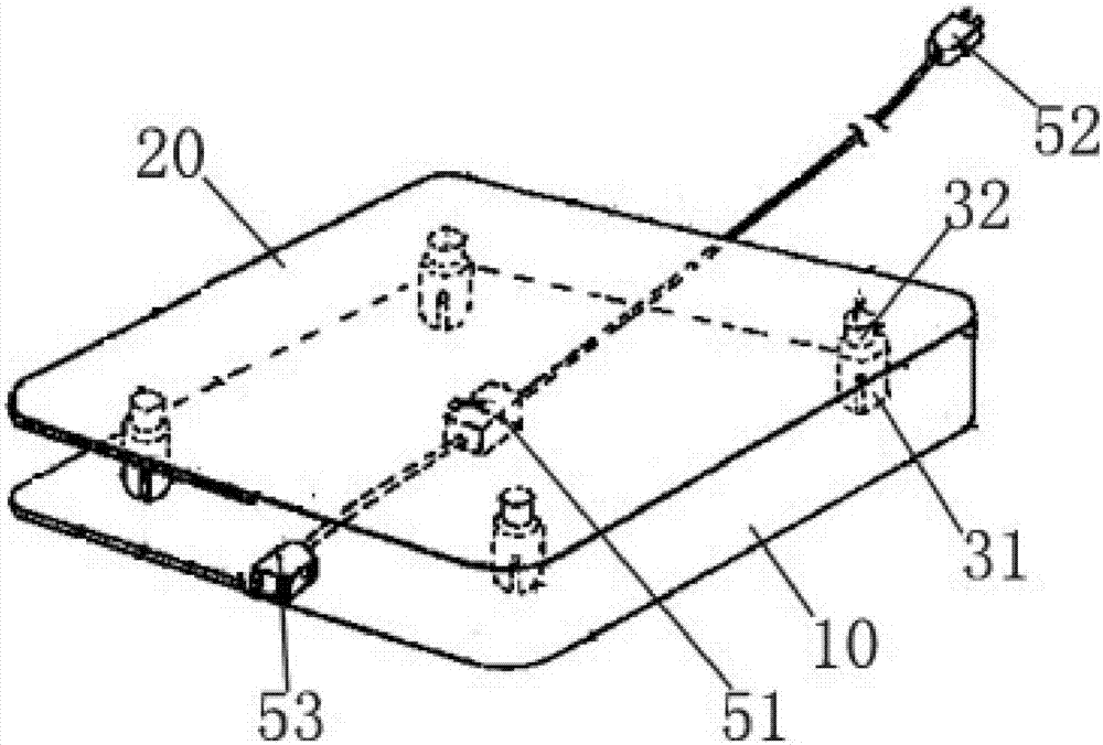
[0021] like figure 1 and figure 2 As shown in the figure, the flat panel switch is used for on-off of short-term electrical equipment such as electric heating pads, ventilation fans, etc. The elastic support mechanism 30 between the plate body 20 and the lower plate body 10 and the switch unit 50 accommodated in the space between the upper plate body 20 and the lower plate body 10 .

[0022] In this embodiment, the lower plate body 10


PUM


Abstract

The present invention proposes a panel switch comprising a lower plate body, an upper plate body, an elastic support mechanism and a switch unit arranged between the upper plate body and the lower plate body, the elastic support mechanism includes a first cylinder body, which is slidably arranged on the second The second cylinder in the first cylinder and the compression springs that are accommodated in the first cylinder and the two ends respectively lean against the lower plate and the upper plate, the side wall of the first cylinder is provided with a strip hole, the second The cylinder body is provided with a protrusion extending into the strip hole. One end of the first cylinder body and the second cylinder body is fixed on the lower plate body, and the other end is kept at a distance from the upper plate body. The first cylinder body and the second cylinder body The other end of the cylinder is fixed on the upper plate, and the other end is kept at a distance from the lower plate. The switch unit includes a micro switch located between the lower plate and the upper plate, and a power supply that is electrically connected to the micro switch and extends to the outside world. The plug is electrically connected with the micro switch and extends to the external power connector. The flat panel switch can be turned on when the user sits on it, and can be turned off when the user leaves, so as to save power.

Description


Claims


Application Information

Patent Timeline
Owner 合肥梦飞电器有限公司
Why Eureka
Try Eureka