Multifunctional cycle power generation system and method by gravity lever

A cycle power generation, multi-functional technology, applied in the direction of engines, machines/engines, mechanical equipment, etc., can solve problems such as failure to meet design requirements, inability to install rotary gear structural parts, large driving force energy consumption, etc., to improve power generation efficiency, Reduce power and save energy

Inactive Publication Date: 2018-09-28
姚裕明
View PDF0 Cites 0 Cited by
  • Summary
  • Abstract
  • Description
  • Claims
  • Application Information

AI Technical Summary

Problems solved by technology

[0002] Power generation equipment generally realizes power generation by converting mechanical kinetic energy into the rotation of electromagnets. Conventional mechanical structures generally realize direct transmission to the transmission shaft through gear transmission. This method not only requires a large driving force and high energy consumption, but also Moreover, rotary gear structural parts cannot be installed in some narrow spaces, so the design requirements cannot be met

Method used


Image

  • Multifunctional cycle power generation system and method by gravity lever
  • Multifunctional cycle power generation system and method by gravity lever
  • Multifunctional cycle power generation system and method by gravity lever

Examples


Embodiment 2

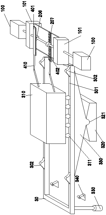
[0041] Embodiment 2: In this embodiment, both ends of the support frame are provided with lifting devices. On the basis of the above structure, another transmission shaft is provided on the side of the counterweight 310 away from the first rack. It is used to drive another group of generators to generate electricity. The transmission shaft is provided with a third one-way clutch 208 and a fourth one-way clutch 209 with the same locking direction. The third one-way clutch 208 and the fourth one-way clutch 209 in this embodiment Set adjacent to the clutch 209, the upper part of the third one-way clutch 208 is provided with the third rack 403 geared with the third one-way clutch 208, the lower part of the fourth one-way clutch 209 is provided with the fourth one-way The clutch 209 is geared to the fourth rack 404 .

[0042] When the third one-way clutch 208 drives the transmission shaft to rotate, the fourth one-way clutch 209 idles, and vice versa, thereby ensuring the one-way r...


PUM


Abstract

The invention provides a multifunctional cycle power generation system and method by a gravity lever. The system comprises a supporting rack and a balance weight arranged on the supporting rack and slidably matched with the supporting rack, wherein engines are arranged on one side or two sides of the balance weight; the input shaft of each engine is connected to a transmission shaft; two or more single-directional clutches are fixedly connected to the middle of the transmission shaft; the locking directions of the single-directional clutches are same, gears are fixed to the peripheries of thesingle-directional clutches, and a rack matched with each gear to drive the transmission shaft to rotate is arranged next to each single-directional clutch; at least one pair of racks is arranged on the upper part and the lower part, separately, the racks and the balance weight which reciprocates are in driving movement and the balance weight is arranged on the supporting rack to swing through a lifting mechanism in a reciprocating manner. As the balance weight which swings in the reciprocating manner pulls the racks to drive the transmission shaft to rotate in the single direction, multiple engines can be driven synchronously to generate electricity synchronously, and the power needed by a supporting rack lifting device is alleviated greatly by means of a swing mode like to a lever, so that the energy sources are saved and the power generation efficiency is improved greatly.

Description

technical field [0001] The invention relates to a gravity lever multifunctional cycle power generation system and method. Background technique [0002] Power generation equipment generally realizes power generation by converting mechanical kinetic energy into the rotation of electromagnets. Conventional mechanical structures generally realize direct transmission to the transmission shaft through gear transmission. This method not only requires a large driving force and high energy consumption, but also Moreover, the rotary gear structural parts cannot be arranged in some narrow space positions, so the design requirements cannot be met. Contents of the invention [0003] The present invention improves the above problems, that is, the technical problem to be solved by the present invention is that the existing power generation equipment requires a large driving force, but the rotary structure must be used to drive power generation. [0004] The specific embodiment of the pr...

Claims


Application Information

Patent Timeline
IPC IPC(8): F03G3/00
CPCF03G3/00
Inventor 姚裕明
Owner 姚裕明
Why Eureka
Try Eureka