High-temperature cabinet

A technology for high-temperature boxes and boxes, which is applied to heating or cooling equipment, laboratory appliances, chemical instruments and methods, etc., can solve the problems of large power consumption and low heat energy utilization rate of high-temperature boxes, and achieve high heat energy utilization rate, The effect of high heating power

Inactive Publication Date: 2017-08-11
NANNING MAOHONG INFORMATION TECH CO LTD
View PDF0 Cites 0 Cited by
  • Summary
  • Abstract
  • Description
  • Claims
  • Application Information

AI Technical Summary

Benefits of technology

This patented technology uses a special type of material called electrically conductive plates that can be used instead of traditional materials like iron or steel when it's needed during cookery. These plates have tiny holes made through them which allow airflow into their interior while still allowing enough space between them to absorb any excess water vapor from inside food products being treated. By covering this area around certain parts of these plates without relying solely upon internal heat sources, they provide more efficient use of thermal power compared to other methods such as burning wood logs at home.

Problems solved by technology

The technical problem addressed in this patented text relates to traditional high temperature devices that use less than optimal heating resources due to their poor efficiency at converting electrical or chemical energy into useful work.

Method used


Image

  • High-temperature cabinet

Examples


Embodiment Construction

[0009] Now do further detailed explanation in conjunction with accompanying drawing.

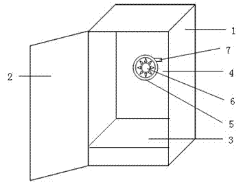
[0010] Such as figure 1 As shown, a high-temperature box includes a box body 1, a box door 2, a box cavity 3 and an air circulation heating device 4, and the air circulation heating device includes a motor 5, a fan 6, and an electric heating element 7, and the air circulation heating The device 4 is electrically connected to the control power supply. The electric heating element 7 is a circular plate metal substrate, and the side of the metal substrate corresponding to the fan 6 is covered with an electrothermal film, and the electrothermal film includes a stainless steel thick film layer.

[0011] The above descriptions are only illustrative specific implementations of the present invention, and are not intended to limit the scope of the present invention. Any equivalent changes and modifications made by those skilled in the art without departing from the concept and principle of the present


PUM


Abstract

The invention relates to a high-temperature box, comprising a box body, a box door, a box cavity and an airflow circulation heating device, the airflow circulation heating device includes a motor, a fan, and an electric heating element, and the airflow circulation heating device is electrically connected to a control power supply, The electric heating element is a disc-shaped metal base, and the side of the metal base corresponding to the fan is covered with an electric heating film, and the electric heating film includes a stainless steel thick film layer.

Description


Claims


Application Information

Patent Timeline
Owner NANNING MAOHONG INFORMATION TECH CO LTD
Why Eureka
Try Eureka