Mixing machine for powder materials

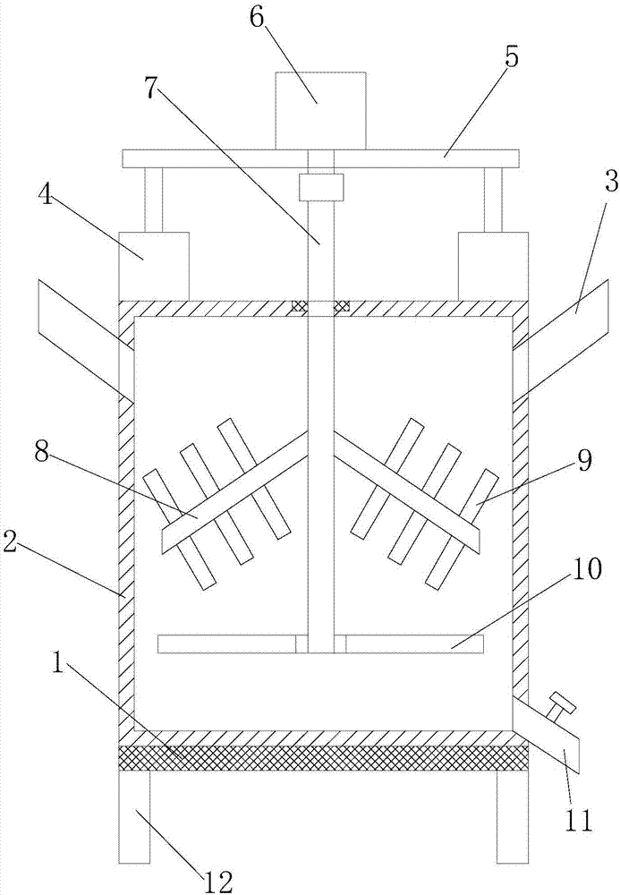
A technology of powder materials and mixers, which is applied in the field of powder processing, can solve problems such as lack of mixing effect, poor uniformity, and slow mixing speed of raw materials back and forth, so as to improve the stirring and mixing effect, enhance stability, and stir and mix. outstanding effect

Inactive Publication Date: 2017-08-29
LIANGXI XUZHONG GENERAL MACHINERY DESIGN STUDIO
View PDF0 Cites 6 Cited by
  • Summary
  • Abstract
  • Description
  • Claims
  • Application Information

AI Technical Summary

Benefits of technology

This technology allows for adding various types of powders into an apparatus by moving them vertically or horizontally along pipes while being driven at high speeds. It uses reducing motors to drive these movements and then use blades on top to mix everything together smoothly without any unevenness. Additionally, it includes stabilizing rods attached between the columns to increase their strengths. Overall this innovation improves the quality and efficiency of the mixture process.

Problems solved by technology

This patented technical problem addressed by this patents relating to conventional dry powered mixers involves uneven distribution of different types of ingredients during their mixing due to rotation caused by slowly moving them around inside an elongated cylindrical tube.

Method used


Image

  • Mixing machine for powder materials
  • Mixing machine for powder materials

Examples


Embodiment Construction

[0016] The following will clearly and completely describe the technical solutions in the embodiments of the present invention with reference to the accompanying drawings in the embodiments of the present invention. Obviously, the described embodiments are only some, not all, embodiments of the present invention.

[0017] Examples of the described embodiments are shown in the drawings, wherein like or similar reference numerals designate like or similar elements or elements having the same or similar functions throughout. The embodiments described below by referring to the figures are exemplary and are intended to explain the present invention and should not be construed as limiting the present invention.

[0018] In describing the present invention, it should be understood that the terms "center", "longitudinal", "transverse", "length", "width", "thickness", "upper", "lower", "front", " Back", "Left", "Right", "Vertical", "Horizontal", "Top", "Bottom", "Inner", "Outer", "Clockwis


PUM


Abstract

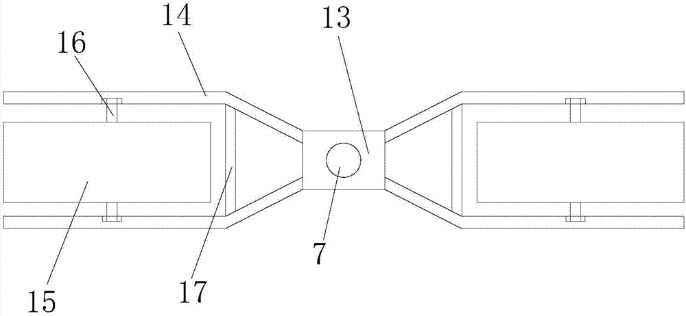
The invention discloses a mixing machine for powder materials. The mixing machine comprises a base, a mixing barrel, feeding pipes, a discharge pipe, lifting mechanisms, a support plate, a gear motor, stirring rods and stirring components, wherein the mixing barrel is fixedly connected to the base, the feeding pipes are arranged on two sides of the upper end of the mixing barrel, the lifting mechanisms are mounted on two sides of the top end of the mixing barrel, two sides of the bottom of the support plate are fixedly connected with the output ends of the corresponding lifting mechanisms, the gear motor is mounted on the support plate, the output end of the gear motor is connected with a rotary shaft, the rotary shaft penetrates the top end of the mixing barrel and extends into the mixing barrel, the plurality of stirring rods are fixedly connected to the part, located inside the mixing barrel, of the rotary shaft, a plurality of stirring standing columns are fixedly connected to the stirring rods, the bottom end of the rotary shaft is fixedly connected with a fixing block, and the symmetrically-arranged stirring components are fixedly connected to two sides of the fixing block. The mixing machine can rotate and move up and down to perform stirring and is outstanding in mixing effect.

Description


Claims


Application Information

Patent Timeline
Owner LIANGXI XUZHONG GENERAL MACHINERY DESIGN STUDIO
Why Eureka
Try Eureka