Energy distribution method for electric vehicle with elastic accumulator
An electric vehicle and energy distribution technology, applied in electric vehicles, electric braking systems, electrical devices, etc., can solve the problems of short battery life, short driving range, poor acceleration performance, etc., to prolong the service life and increase the The effect of driving mileage and improving acceleration
- Summary
- Abstract
- Description
- Claims
- Application Information
AI Technical Summary
Problems solved by technology
Method used
Image

Examples
Example Embodiment
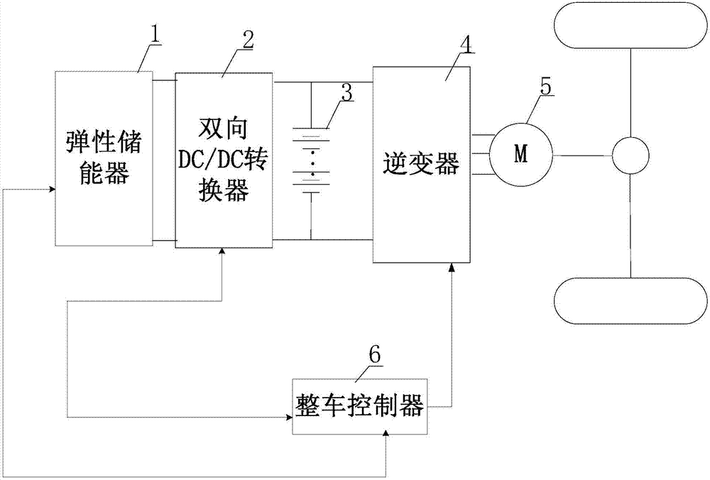
[0028] Specific implementation mode one, combination figure 1 with Figure 4 Explaining this embodiment, the method for energy distribution of electric vehicles with elastic energy storage described in this embodiment is implemented based on the energy distribution system of electric vehicles with elastic energy storage, and electric vehicles with elastic energy storage The energy distribution device includes elastic energy storage 1, two-way DC / DC converter 2, lithium iron phosphate battery pack 3, inverter 4, drive motor 5 and vehicle controller 6;
[0029] The DC input and output end of the elastic energy storage device 1 is connected to one input and output end of the bidirectional DC / DC converter 2, and the other current input and output end of the bidirectional DC / DC converter 2 is simultaneously connected to the charge and discharge signal of the lithium iron phosphate battery pack 3. Terminal and the DC current input and output terminals of the inverter 4;
[0030] The
Example Embodiment
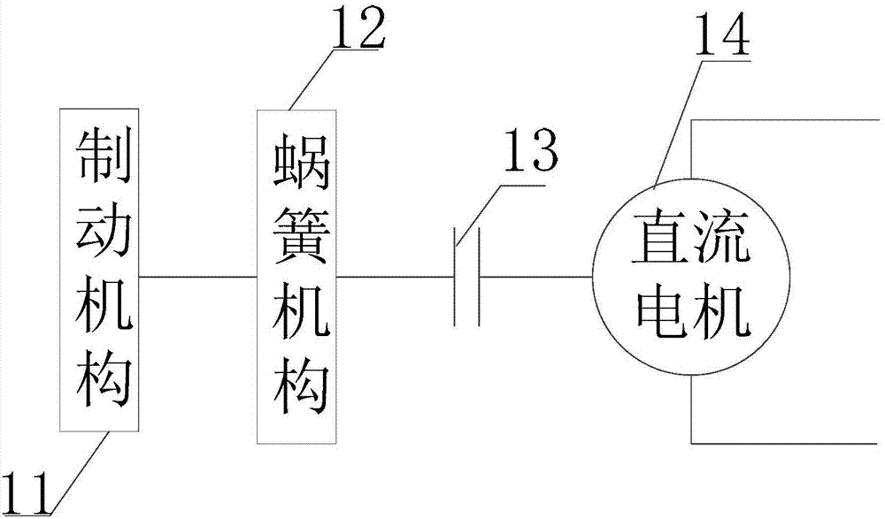
[0042] Specific implementation mode two, combination figure 2 To explain this embodiment, this embodiment is a further explanation of the energy distribution method of an electric vehicle with an elastic accumulator described in the first embodiment. The elastic accumulator 1 includes a brake mechanism 11, a vortex spring mechanism 12, a clutch 13 And DC motor 14;
[0043] The vortex spring mechanism 12 and the braking mechanism 11 are both sleeved on a transmission shaft, the transmission shaft is coaxially connected with the output shaft of the DC motor 14, and the power terminal of the DC motor 14 is connected to one of the bidirectional DC / DC converters 2. Current signal input and output terminals; a clutch 13 is provided between the output shaft of the DC motor 14 and the transmission shaft.
Example Embodiment
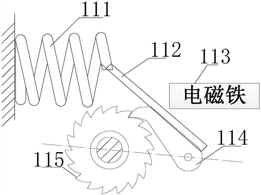
[0044] Specific implementation mode three, combination image 3 To explain this embodiment, this embodiment is a further explanation of the energy distribution method of an electric vehicle with elastic energy storage described in the first embodiment. The braking mechanism 11 includes a housing, a spring 111, a metal rod 112, and an electromagnet. 113, pawl 114 and ratchet wheel 115;
[0045] One end of the spring 111 is fixed on the side wall of the housing, and the other end of the spring 111 is fixedly connected to one end of the metal rod 112. The metal rod 112 is arranged between the electromagnet 113 and the pawl 114, and the electromagnet 113 and the metal rod 112 There is a gap therebetween, and the metal rod 112 is located in the magnetic field of the electromagnet. The front end of the pawl 114 is engaged in the teeth of the sub-ratchet wheel 115, and the rear end of the pawl 114 is movably connected with the side wall of the housing.
PUM
 Abstract
Description
Claims
Application Information
 - R&D Engineer
- R&D Manager
- IP Professional
- Industry Leading Data Capabilities
- Powerful AI technology
- Patent DNA Extraction
Browse by: Latest US Patents, China's latest patents, Technical Efficacy Thesaurus, Application Domain, Technology Topic.
© 2024 PatSnap. All rights reserved.Legal|Privacy policy|Modern Slavery Act Transparency Statement|Sitemap