Hydraulic liftable device of traction bed

A lifting device and traction bed technology, applied in the field of traction beds, can solve problems such as unfavorable installation and disassembly, inability to ensure the stability of lifting, and insufficient comfort in use, and achieve convenient disassembly and assembly, user-friendly use, comfortable lifting and humanization Effect

Inactive Publication Date: 2017-11-07
谭晓晶
View PDF0 Cites 1 Cited by
  • Summary
  • Abstract
  • Description
  • Claims
  • Application Information

AI Technical Summary

Benefits of technology

This patented technology allows an improved lift system for vehicles such as trucks or boats without requiring expensive equipment like cranes or winches. It achieves this through regulating its movement based on factors like weight, cargo size, etc., allowing it to be customizable according to individual needs while maintaining safety standards. Additionally, there're also provided various technical features related thereto including stabilizing the entire structure during operation, providing support when needed, ensuring proper alignment over multiple parts, reducing noise from moving components, simplifying construction processes, improving ease of handling, being easily assembled/disassembleled, and promoting durability.

Problems solved by technology

This patented technology uses special materials called Mechanism Belt (MB) or Shear Force Plate System (SFPS), which are made up from tiny particles attached together like threads on rods. These small objects help keep these structures stable during movement between different levels within an organism's body.

Method used


Image

  • Hydraulic liftable device of traction bed
  • Hydraulic liftable device of traction bed

Examples


Embodiment

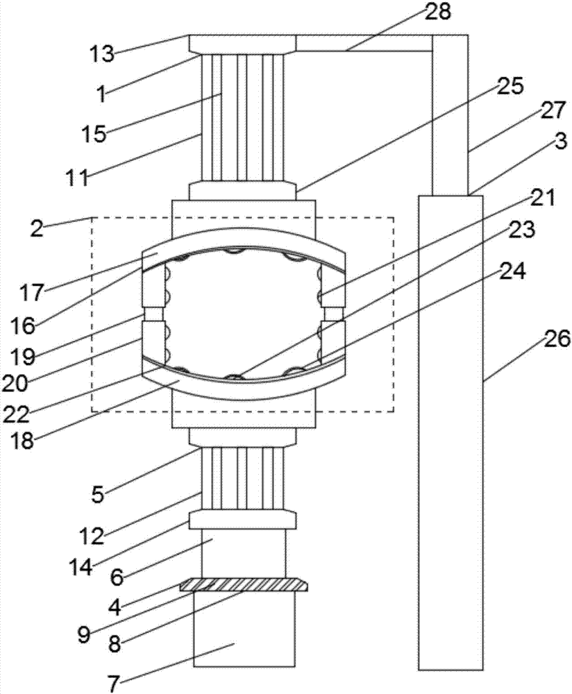
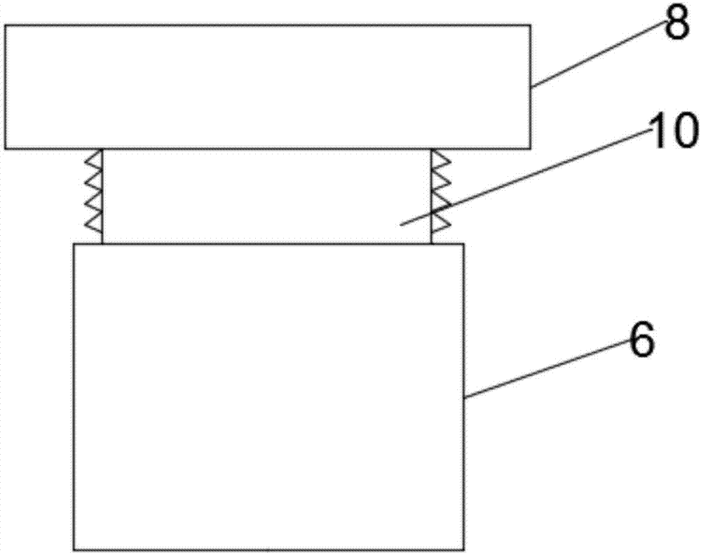
[0019] see figure 1 , figure 2 , the present invention provides a technical solution: a hydraulic liftable device for a traction bed, including an adjustment device 1, a mounting device 2 and a support rod 3, the adjustment device 1 includes an adjustment rod 4 and a buffer frame 5, and the adjustment rod 4 includes a fixed rod 6 and a hydraulic rod 7, the hydraulic rod 7 and the fixed rod 6 are connected together through a connecting seat 8, the buffer frame 5 includes an upper buffer rod 11 and a lower buffer rod 12, and the upper buffer rod 11 and the support rod 3 are connected together, the top of the fixed rod 6 is equipped with a mounting seat 14, the lower buffer rod 12 and the mounting seat 14 are connected together, the upper buffer rod 11 and the lower buffer rod 12 adopt the same structure, Both the upper buffer rod 11 and the lower buffer rod 12 are composed of several spring rods 15, which are arranged in a ring between the spring rods 15, and the installation dev


PUM


Abstract

The invention discloses a hydraulic liftable device of a traction bed, which comprises an adjustment device, a mounting device and a support rod, the adjustment device includes an adjustment rod and a buffer frame, the adjustment rod includes a fixed rod and a hydraulic rod, the hydraulic rod and the fixed rod pass The connecting seats are connected together, the buffer frame includes an upper buffer rod and a lower buffer rod, the upper buffer rod and the support rod are connected together, the top of the fixed rod is equipped with a mounting seat, the lower buffer rod and the mounting seat are connected together, the upper The buffer rod and the lower buffer rod adopt the same structure. Both the upper buffer rod and the lower buffer rod are composed of several spring rods, and the spring rods are arranged in a ring. The installation device includes a mounting frame, and the mounting frame includes an upper mounting plate and a lower mounting plate. The installation plate, the device can fully ensure the stability of the overall lifting through the mutual cooperation of the upper buffer rod and the lower buffer rod.

Description


Claims


Application Information

Patent Timeline
Owner 谭晓晶
Why Eureka
Try Eureka