Oil injector with double air inlet channels

A fuel injector and double-injection technology, which is applied in the direction of fuel injection control, machine/engine, fuel injection device, etc., can solve the problems of unfavorable fuel consumption, reduction, engine power waste, etc., to achieve supply, fast response speed, Flexible and changeable fuel injection schedule

Active Publication Date: 2017-12-26
CHINA FIRST AUTOMOBILE
View PDF5 Cites 5 Cited by
  • Summary
  • Abstract
  • Description
  • Claims
  • Application Information

AI Technical Summary

Problems solved by technology

Under such a high injection pressure, the atomization effect of fuel is greatly improved, and simply increasing the injection pressure will cause a waste of engine power, which is not conducive to the reduction of fuel consumption

Method used


Image

  • Oil injector with double air inlet channels
  • Oil injector with double air inlet channels
  • Oil injector with double air inlet channels

Examples


Example Embodiment

[0025] The present invention will be further described below in conjunction with specific drawings and embodiments.

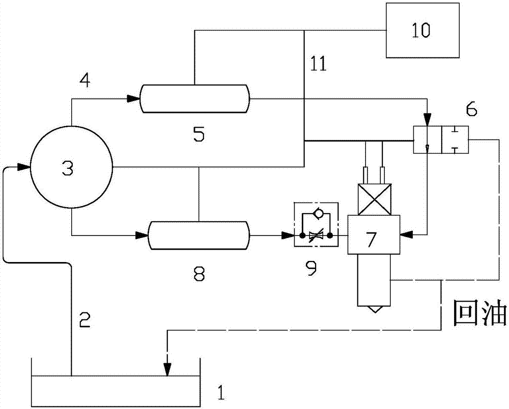
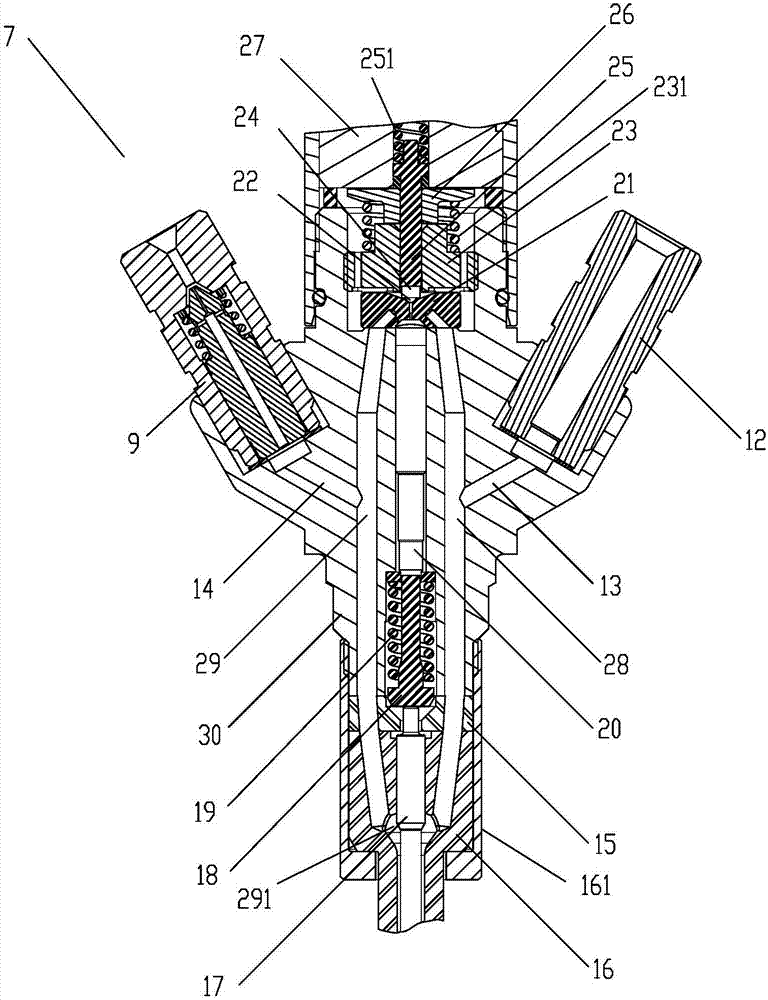
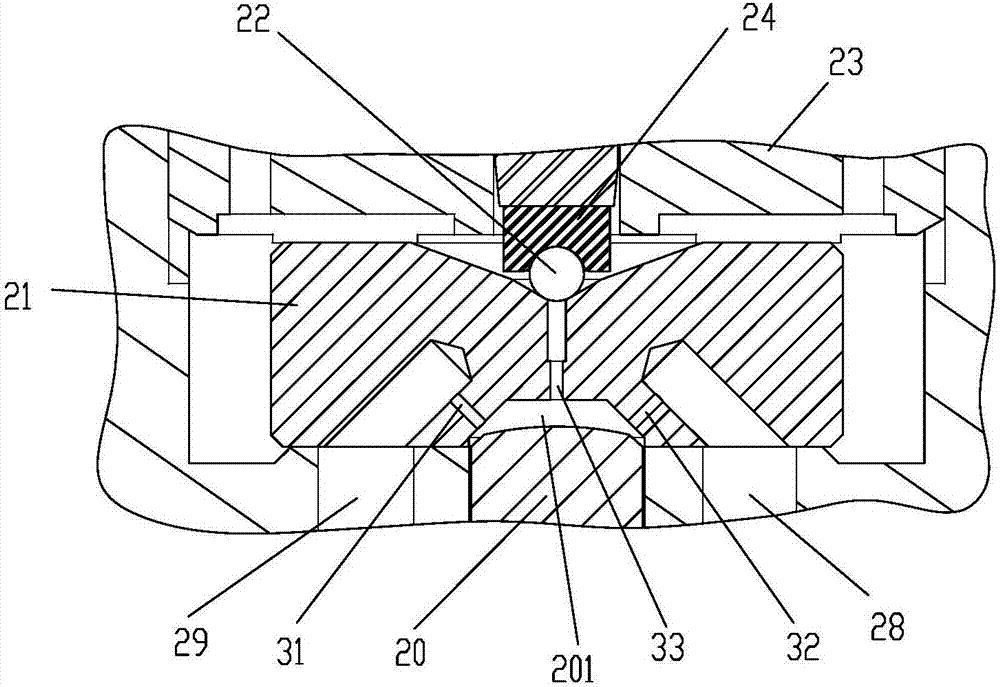
[0026] In order to be able to realize the flexible switching of the two injection pressures in a single injection cycle, such as figure 1 As shown, a fuel supply system for a diesel engine includes a fuel tank 1, a low-pressure fuel pipe 2, a high-pressure fuel pump 3, a high-pressure fuel pipe 4, a high-pressure common rail pipe 5, a middle and low-pressure common rail pipe 8, a solenoid switch valve 6, and a dual-inlet fuel injection port. Oiler 7, check valve with orifice 9, ECU (Electronic Control Unit) 10 and electronic control wiring harness 11;

[0027] Fuel tank 1 is connected to high pressure fuel pump 3 through low pressure fuel pipe 2; high pressure fuel pump 3 is connected to high pressure common rail pipe 5 and medium and low pressure common rail pipe 8 through high pressure fuel pipe 4; high pressure fuel pump 3 is an electronically controlled multi-cylind


PUM


Abstract

The invention provides an oil injector with double air inlet channels. The oil injector comprises an oil injector body, a first oil inlet channel, a second oil inlet channel, an electromagnet, an armature, an armature rod, a ball seat, a control valve seat, a first spring, a ball valve, a throttling hole plate, a control piston, a second spring, an ejector rod, a needle valve, a needle valve body, a transition block, a first oil inlet hole, a second oil inlet hole and an oil injection nozzle, wherein the oil injector body, the transition block and the needle valve body are assembled from top to bottom into a whole the first oil inlet channel and the second oil inlet channel are positioned in the oil injector body, the transition block and the needle valve body; in the down direction, the first oil inlet channel and the second oil inlet channel both communicate with the oil injection hole channel of the oil injection nozzle; and in the up direction, the first oil inlet channel and the second oil inlet channel correspondingly communicate with a first oil inlet throttling hole and a second oil inlet throttling hole which are formed in the throttling hole plate. The oil injector can be applied to a diesel engine fuel oil supply system of which the oil injection rate is variable and adjustable at any time; the injection demand at different pressure can be met; and accordingly, the engine combustion heat release rate can be improved and the emission can be reduced.

Description


Claims


Application Information

Patent Timeline
Owner CHINA FIRST AUTOMOBILE
Why Eureka
Try Eureka