Manufacturing technology of Wolter-I type precision core shaft

A manufacturing process and mandrel technology, which is applied in the field of machining Wolter-I type precision mandrels with 2-axis machine tools, can solve the problems of high manufacturing cost and difficult processing of high-precision Wolter-I type mandrels, etc., and improve the surface profile shape. The effect of precision, reduction of total machining allowance, and reduction of manufacturing cost

Active Publication Date: 2018-01-12
HARBIN INST OF TECH
View PDF7 Cites 9 Cited by
  • Summary
  • Abstract
  • Description
  • Claims
  • Application Information

AI Technical Summary

Problems solved by technology

[0005] Aiming at the problems of difficult processing and high manufacturing cost of high-precision Wolter-I type mandrels, the present invention improves and optimizes the proces

Method used


Image

  • Manufacturing technology of Wolter-I type precision core shaft
  • Manufacturing technology of Wolter-I type precision core shaft
  • Manufacturing technology of Wolter-I type precision core shaft

Examples


example

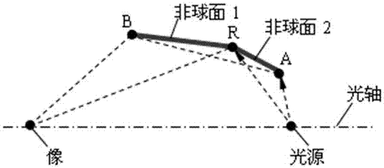
[0044] Taking the Woler-I mandrel composed of ellipsoidal surface and hyperboloid as an example for actual processing, it has undergone rough turning (measurement), electroless nickel-phosphorus alloy plating, fine turning (measurement), automatic polishing (measurement) and manual correction polishing. Manufactured with the largest caliber Φ The mandrel is 170.81mm, and the measured surface roughness of the sample is RMS1.56nm, which can meet the application requirements of extreme ultraviolet light with a wavelength below 100nm.


PUM

PropertyMeasurementUnit
Particle sizeaaaaaaaaaa
Thicknessaaaaaaaaaa

Abstract

The invention discloses a manufacturing technology of a Wolter-I type precision core shaft. The technology process comprises the following steps: acquiring an aluminum alloy round bar material blank,performing two-step core shaft blank rough turning, performing measuring, performing chemical plating of an nickel-phosphorus alloy on the surface of a core shaft, performing low-cost precise turningon the core shaft, performing measuring, performing low-cost automatic polishing on the core shaft, performing measuring, performing manually-corrected polishing on the core shaft, performing measuring and finishing the core shaft. According to the manufacturing technology of the Wolter-I type precision core shaft, in the process of manufacturing technology of a Wolter-I type reflector, in order to guarantee the precision of a machining contour, a method that a tool center moves along an equidistant line of a to-be-machined track is adopted in manufacturing of the optical core shaft for copying, the turning and polishing process of the optical core shaft is completed in an X-and-Z two-axis computer numerical control machine tool, thus the shape precision of the surface contour of the coreshaft after turning and polishing is improved, equipment cost and machining cost for turning, grinding and polishing by using a multi-axis computer numerical control machine tool with more than threeaxes are reduced, and therefore, the manufacturing cost of the optical core shaft for copying and the Wolter-I type reflector is reduced.

Description


Claims


Application Information

Patent Timeline
Owner HARBIN INST OF TECH
Why Eureka
Try Eureka