Door glass guiding part for shower room

A guide and shower room technology, applied in the field of shower room appliances, can solve the problems of inconvenience, glass sliding doors cannot move freely, etc., and achieve the effect of convenient use

Pending Publication Date: 2018-03-06
PINGHU XINDA ELECTRONICS PLASTIC
View PDF3 Cites 0 Cited by
  • Summary
  • Abstract
  • Description
  • Claims
  • Application Information

AI Technical Summary

Benefits of technology

This patented technology allows for securely fixing an opening through a window frame with a movable panel or plate inside it without falling out easily during movement. It also includes a mechanism where when there are two different movements between the panes (movement), they move smoothly along their way instead of getting stuck).

Problems solved by technology

The technical problem addressed by this patented solution for improving the functionality or usability of an electronic device's display window (such as that found inside a bathroom).

Method used


Image

  • Door glass guiding part for shower room

Examples


Embodiment Construction

[0009] Below in conjunction with accompanying drawing and embodiment the present invention is further described:

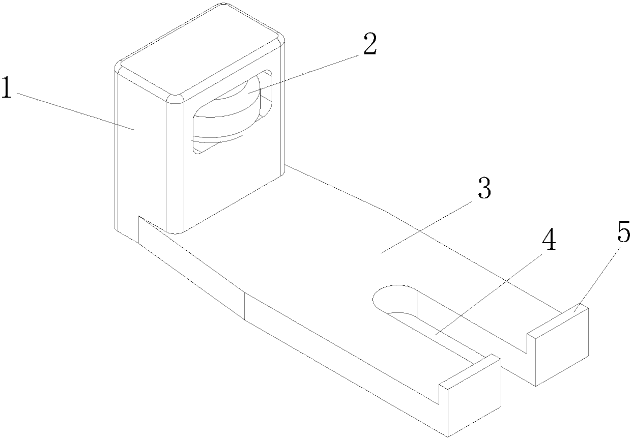
[0010] As shown in the figure, a door glass guide for a shower room includes a body, the body is provided with a column 1, and the column 1 is provided with a guide hole, and a guide wheel 2 is provided in the guide hole. The main body is provided with a protruding installation arm 3 , a screw slot 4 is provided on the installation arm 3 , and a protruding clip 5 is provided at the end of the installation arm 3 .

[0011] The body is integrally formed.

[0012] In actual use, the door glass guide of the present invention is fixed by the mounting arm and the screw groove on the mounting arm, and then the sliding door glass is placed on the mounting arm, and the guide wheels are close to the sliding door glass. When moving, the guide wheels on the column play a guiding role, and the glass sliding door is not easy to escape from the sliding track, which is convenient t


PUM


Abstract

The invention discloses a door glass guiding part for a shower room. The door glass guiding part comprises a main body, wherein a vertical column is arranged on the main body; a guiding hole is formedin the vertical column; a guiding wheel is arranged in the guiding hole; an extended mounting arm is arranged on the main body; a screw groove is formed in the mounting arm; and a convex clamping part is arranged at one end part of the mounting arm. The door glass guiding part disclosed by the invention is fixed through the mounting arm and the screw groove in the mounting arm; then, sliding doorglass is arranged on the mounting arm and the guiding wheel clings to the sliding door glass; and when the sliding door glass moves left and right, the guiding wheel on the vertical column achievinga guiding effect, so that a glass sliding door is not easy to fall out of a sliding rail and is convenient to use.

Description


Claims


Application Information

Patent Timeline
Owner PINGHU XINDA ELECTRONICS PLASTIC
Why Eureka
Try Eureka